PiFlux · Volume 6
Full Build with All Add-Ons
Step-by-step assembly of the PiFlux Barebones Kit with Pi 5 and every available add-on module installed
6.1 Before You Begin
Carbon Computers publishes one genuine primary-source assembly document for the PiFlux: a 13-page PDF titled “Pi Flux r.1 — Build Guide”, linked from the product page’s pre-order section. It is the source for Sections 2, 3, and 8 below, walking the barebones-chassis-plus-Pi-5 build in real photographs with an exact component list, screw sizes, and cable-routing notes. It does not cover the M.2 Mod, either Radio option, the External WiFi Mod, or the Active Cooling System as installation procedures — those four are absent from the guide entirely. Sections 4 through 7 therefore work from the module interfaces Volumes 3 and 5 already establish rather than a confirmed Carbon Computers sequence, and are hedged accordingly. The product page states the practical consequence directly: add-ons “bundled with your Flux purchase” are installed by Carbon Computers before shipment, but “if ordered as barebones, it can’t be installed by us; you will receive a part kit for DIY.”
6.1.1 Bill of materials for the full build
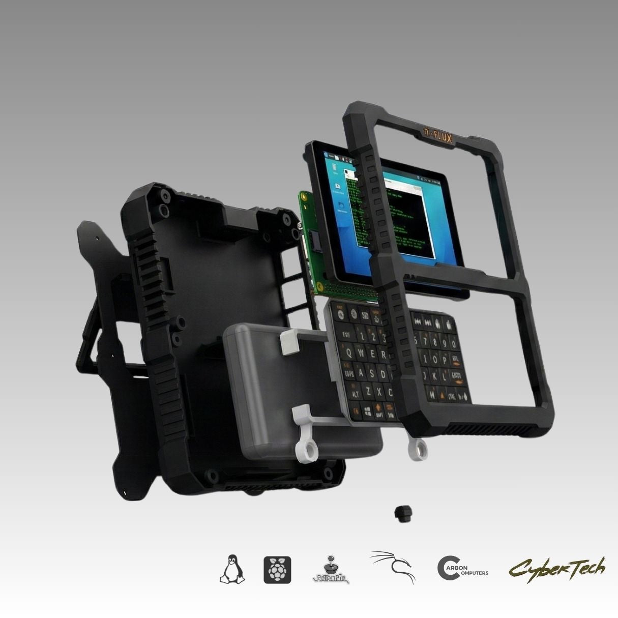
The base-build bill of materials below is transcribed directly from the r.1 Build Guide’s “Getting Started” page. The add-on rows are not part of that guide; they are carried over from Volume 5’s catalog treatment and are marked accordingly.
Table 1 — 1.1 Bill of materials for the full build
| Part | Source | Notes |
|---|---|---|
| 5-inch Waveshare DSI display | Barebones Kit | Two FPC video cable lengths ship with the display — see §3.2 |
| Mini keyboard | Barebones Kit | Disassembled and mounted into the front face — see §3.2 |
| INIU 10,000 mAh battery | Barebones Kit | A USB-C power-bank unit, not a bare cell — see §2 |
| MicroSD card extender | Barebones Kit | Routes the SD slot to an externally accessible position |
| USB-C “U-shape” adapter | Barebones Kit | Feeds the Pi 5’s USB-C power input from the battery through the pull-switch mechanism |
| Key ring for the top pull switch | Barebones Kit | Attaches to the physical power switch — see §2 |
| Raspberry Pi 5, 4–16 GB | Buyer-supplied (Barebones path) or pre-installed | See Volume 2 for RAM tier selection |
| Pi 5 cooler | Barebones Kit | An active (fan-equipped) cooler — see §7 for the tension this creates with the catalog’s separate “Active Cooling System” line |
| M2.5×10 mm screws, ×6 | Barebones Kit | 4 of the 6 optionally secure the Pi 5 to the display back-to-back |
| M2×4 mm screws | Barebones Kit | Secure the optional rear MOLLE/back-attachment panel |
| 3D-printed chassis parts | Barebones Kit | Bottom part, top/face part, internal keyboard support, internal bottom power button, internal top pull-switch housing, back attachment |
| M.2 Mod (PCIe-to-M.2 HAT+, FFC cable, standoffs) | Add-on purchase | Volume 3; installation not covered by the r.1 guide |
| NVMe drive, 2230 or 2242 | Buyer-supplied | Volume 3 §2 |
| Base Radio or Advanced Radio board | Add-on purchase | GPS+LoRa combo HAT; installation not covered by the r.1 guide |
| External USB SDR dongle (Advanced Radio only) | Bundled with Advanced Radio | See §5.2 |
| External WiFi Mod (USB adapter + antenna pigtail) | Add-on purchase | Installation not covered by the r.1 guide |
| Active Cooling System | Add-on purchase | See §7 for the open question of whether this duplicates the stock Pi 5 cooler above |
For a buyer ordering add-ons bundled with a complete unit, Carbon Computers assembles, tests, and configures the whole thing before shipment — none of this is the buyer’s problem in that path. This volume is written for the Barebones Kit buyer, or the complete-unit owner adding a module after the fact, doing the installation themselves.
6.1.2 Tools required
The r.1 guide’s photographs show no tool beyond a small Phillips-head precision screwdriver sized to the M2 and M2.5 screws above, and fingers — its language for priming a tight USB port opening is literally “widen with your fingers.” Tape is worth having for securing the longer FPC video cable if that variant is used (§3.2), and a nylon spudger is a sensible (if unlisted) addition for working the chassis halves without marking the finish. No soldering is documented anywhere in the base build. For the add-ons in Sections 4–7, expect the same small driver and the same care around FFC ribbon cables; an SMA wrench helps with the antenna connectors in Section 9. No published tool list exists for the add-on installs specifically — this is inferred from the interfaces in Volumes 3 and 5, not confirmed by Carbon Computers.
6.1.3 Assembly sequence overview
The order below follows the r.1 guide’s own structure for Sections 2, 3, and 8, with the four undocumented add-on steps inserted at the point their physical interfaces make most sense — before the chassis halves close, so that nothing already-installed has to be disturbed to reach them:
- Inspect the barebones parts and the battery, keyboard, and display components.
- Assemble the bottom part — bottom power button, microSD extension, then battery position and cable routing (§2).
- Mount the Pi 5 (cooler already attached) and display as one subassembly, connecting the FPC video cable (§3).
- Mount the USB-C U-shape adapter to its carrier and connect the microSD extension to the Pi 5, checking cooler clearance (§3.2, §10).
- [Undocumented] Install the M.2 Mod and NVMe drive on the subassembly before it goes into the chassis (§4).
- [Undocumented] Install the Radio module and, if applicable, the External WiFi Mod’s internal adapter (§5, §6).
- Fit the combined subassembly into the chassis at an angle, connect the battery and all cables, remove the display’s protective film, mount the keyboard support frame (§3.2).
- Disassemble and mount the keyboard into the front face (§3.2).
- [Undocumented] Mount the Active Cooling System, if distinct from the stock cooler fitted in step 3 (§7).
- Mount the front face, secure with the six back screws, fit the key ring, power-on test before final closure (§2, §10).
- Optionally fit the rear MOLLE/back-attachment panel (§2).
- Flash and configure the microSD card, run first boot (§8).
- Route and mount the external antennas (§9).
The middle three add-on steps (5, 6, 9) are this volume’s own synthesis, not a transcription of anything Carbon Computers has published — treat them as the most reasonable placement given the module interfaces in Volumes 3 and 5, and confirm specifics with Carbon Computers support (Section 12) before an irreversible mounting choice.
6.2 Step 1 — Prepare the Barebones Chassis
The barebones kit arrives as five 3D-printed parts — bottom part, top/face part with the keyboard opening, internal keyboard support frame, internal bottom power-button housing, internal top pull-switch housing (built around the USB-C U-shape adapter), and an optional back-attachment panel — plus the INIU 10,000 mAh battery, microSD extender, USB-C adapter, key ring, and mounting screws. The INIU unit is worth naming precisely: a self-contained USB-C power bank with its own fast-charge circuitry and status indicator, not a bare LiPo cell needing a separate charge/protection board — no cell-level wiring to get wrong, though its housing occupies more volume than a custom PCB would.
Bottom-part assembly: insert the bottom power button (gating the battery, distinct from the top pull switch that gates the Pi 5 — §3.2), mount the microSD extension, then position the battery and route its power cable, per the guide. Its photographs show the battery flat against the bottom part, output cable and microSD ribbon dressed clear of the screw bosses.
The guide instructs the opposite of what might be assumed about the display’s protective film: it comes off only after the Pi 5/display subassembly is mounted into the chassis (§3.2), protecting the panel through the handling in between. There is no documented statement that the battery ships disconnected for shipping safety; since the INIU unit is a power bank with its own switch, that concern is less pressing than for a bare cell.
6.3 Step 2 — Seat the Raspberry Pi 5
6.3.1 Pi 5 orientation and connector alignment
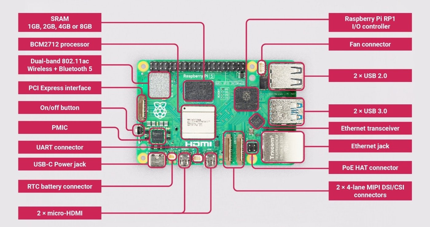
The Pi 5 carries a 4-pin fan connector adjacent to the USB-C power jack, a PCIe FFC connector next to the USB ports, and two 4-lane MIPI DSI/CSI ribbon connectors along one edge — feeding the Active Cooling System (§7), the M.2 Mod (§4), and the display (§3.2) respectively. The r.1 guide’s photographs show the cooler mounted to the board first, before the Pi 5 is ever paired with the display, its spring-loaded retention screws going into the board’s four stock mounting holes ahead of everything else in this section.
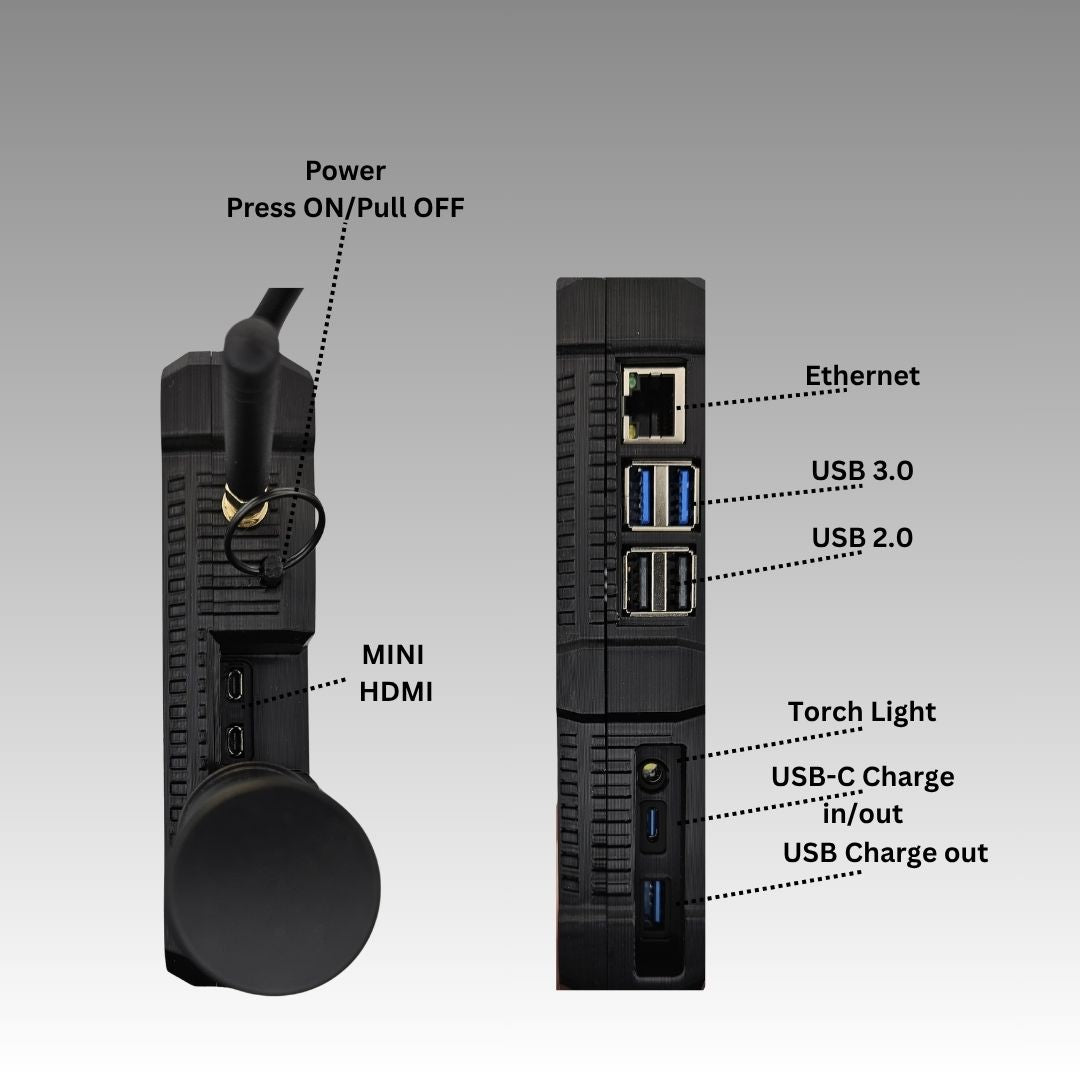
Once assembled into the finished chassis, the Pi 5’s own physical port stack — two micro-HDMI, two USB 3.0, two USB 2.0, Ethernet, and USB-C power/charge — stays externally accessible on the unit’s side edge, alongside a small torch light. Carbon Computers’ own assembled-unit photography (Figure 6.4) confirms this directly, labeling “MINI HDMI” on one face and “Ethernet / USB 3.0 / USB 2.0 / Torch Light / USB-C Charge in/out / USB Charge out” on the other: the Pi 5’s external I/O is not sacrificed by the internal DSI display — both exist side by side, the display on the Pi 5’s DSI ribbon connector, the external ports free for a monitor, peripherals, or wired networking.
The guide gives no screw-torque figure or standoff-height spec for mounting the Pi 5 board — its only fastener guidance anywhere is “DO NOT overtighten screws, snug fit them, and test before closing” (§10), which this volume takes as the operative instruction for every screw in the build.
6.3.2 Display and keyboard connections
The display connects to the Pi 5 over DSI, not HDMI — worth stating plainly, since the Pi 5’s exposed micro-HDMI ports (Figure 6.4) are for an external monitor, separate from the internal panel. Carbon Computers’ display-configuration documentation is explicit: an “FFC Cable 22PIN 200mm” runs the display’s DSI port to the Pi 5’s 22-pin DSI connector, and a separate GPIO lead supplies the display’s 5 V/GND power rather than routing it through the video ribbon. The r.1 guide adds a detail the display page doesn’t: the display ships with two FPC video cables of different lengths — short (tight but usable), long (easier to route, but must be taped down since nothing else holds it once routed). The guide’s photographs show both, labeled accordingly.
Before the Pi 5/display pair goes near the chassis, four of the six M2.5×10 mm screws optionally join the Pi 5 board directly to the back of the display, per the display-configuration documentation (“secure the Raspberry Pi to the display with M2.5 screws”) — one rigid subassembly before it ever reaches the chassis.
One spec-sheet inconsistency is worth flagging rather than silently resolving: Volume 1 carries the display resolution as 1920×720, from Carbon Computers’ product page. The panel named in the r.1 guide’s bill of materials is a Waveshare 5-inch DSI display, and Waveshare’s DSI panels this size are natively 720×1280 portrait, rotated to landscape in software (§8) — which doesn’t arithmetically produce 1920×720. This volume can’t resolve which figure is correct; it is flagged [VERIFY against the physical unit or a resolution reading from the running desktop] as an inconsistency in Carbon Computers’ own materials, not an invention here.
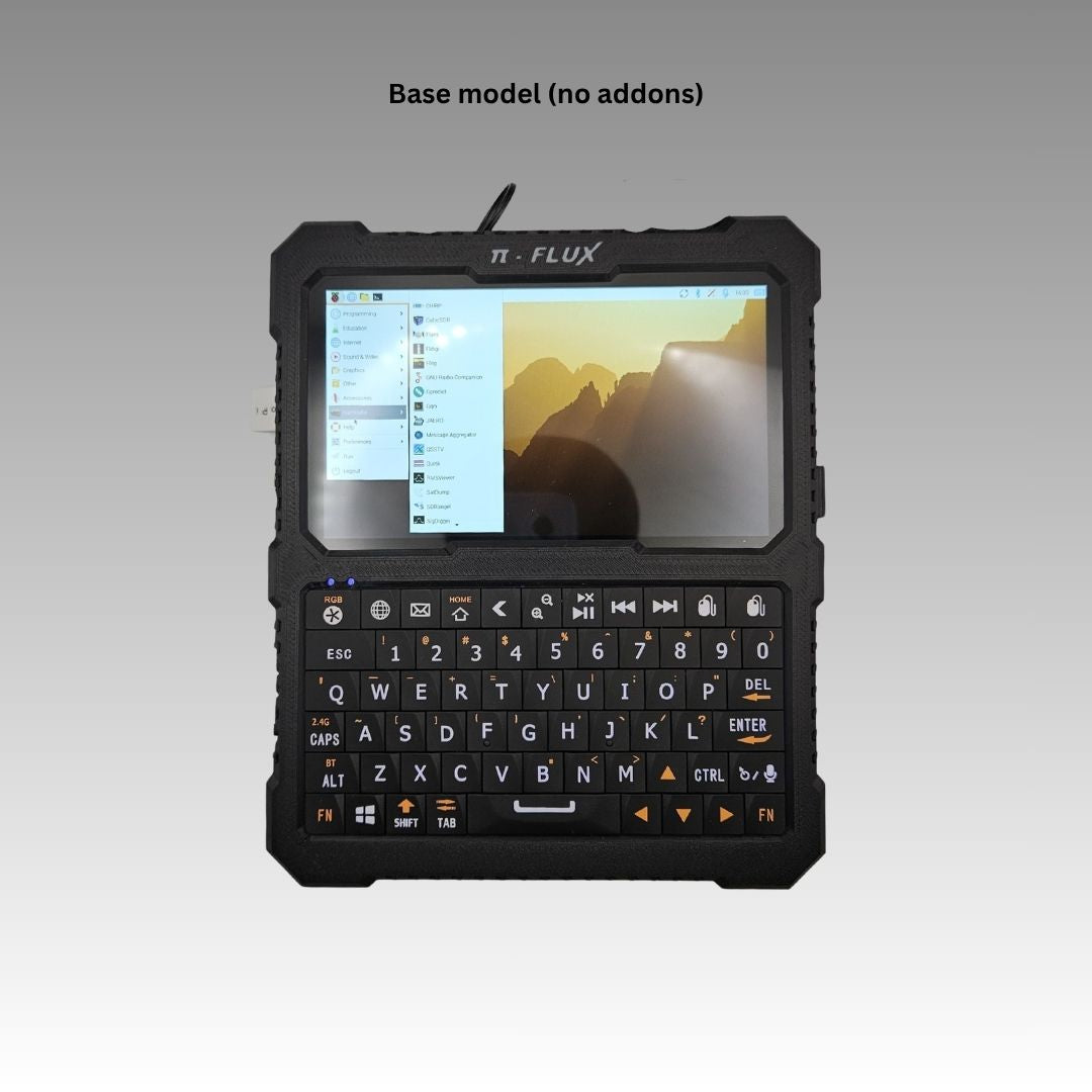
The keyboard is Carbon’s chosen mini wireless keyboard (a Keychron B1), and the r.1 guide disassembles it from its retail shell and mounts the bare PCB directly into the front face — per “take the keyboard apart and mount to the front part (face).” By default it keeps its own wireless link: the keyboard’s 2.4 GHz USB receiver is mounted internally and brought out at the “KB Dongle” port labeled on the side edge in Figure 6.14 (§9), with Bluetooth as its other native mode — so the “KB Dongle” is the documented default, not an unreconciled port. Carbon also documents an optional alternative: wiring the keyboard directly to the Pi 5’s 3.3 V GPIO instead, which pairs with the front-face variant that has no side cutout; a second front-face variant with larger holes for brass threaded inserts is the other option Carbon shows (which of the two a builder uses appears to track the wireless-vs-GPIO choice rather than being purely cosmetic — [VERIFY against the guide’s own variant labeling]). One gotcha worth carrying forward: the guide says to “move the battery wire up to prevent the frame pinch” as the keyboard support frame and front face come together, or the battery’s own power lead gets caught.
6.4 Step 3 — Install the M.2 Mod and NVMe Drive
Nothing in this section is confirmed by a Carbon Computers-published source. The r.1 Build Guide does not mention the M.2 Mod at all, and no other primary source documents its chassis-specific mounting position, screw sizes, or clearance to the Pi 5 board. What follows is built from the M.2 Mod’s own interface, as Volume 3 already establishes it — the Pi 5’s PCIe 2.0 lane, broken out through the RP1 I/O controller to an FFC connector next to the USB stack, feeding a Waveshare-style PCIe-to-M.2 HAT+ board.
6.4.1 Mount the M.2 Mod board
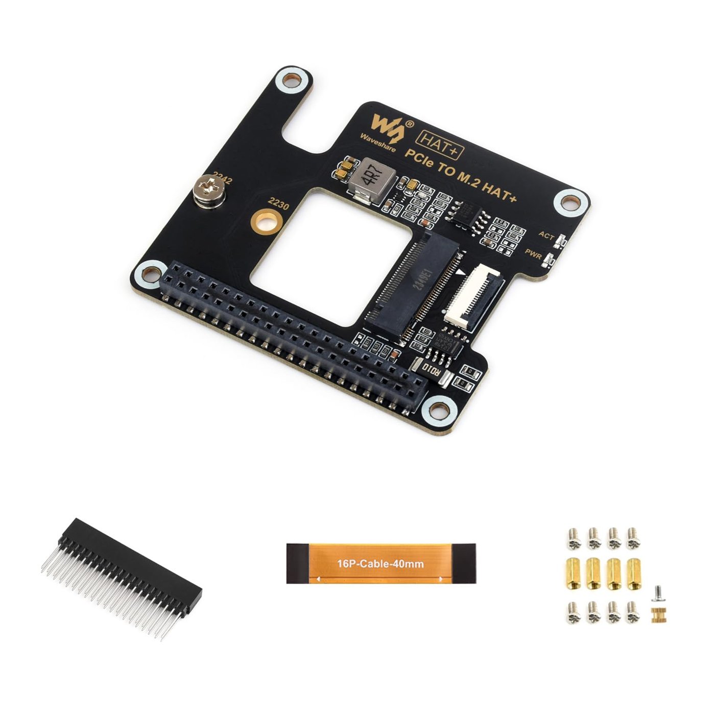
A representative M.2 HAT+ of this family ships with brass standoffs, a 40-pin GPIO header for mechanical stacking, and a short 16-pin FFC cable for the PCIe signal path itself, rather than routing PCIe over GPIO. The board mounts above the Pi 5 on the standoffs, aligned to its mounting holes, with the FFC cable running from the HAT+‘s PCIe connector to the Pi 5’s PCIe FFC connector next to the USB ports. Whether the PiFlux chassis stacks the M.2 Mod directly above the Pi 5 this way, or reserves a separate compartment reached by a longer cable, is [VERIFY from Carbon Computers directly] — the chassis’s internal add-on layout is not shown in any source retrieved for this volume.
6.4.2 Seat and secure the NVMe drive
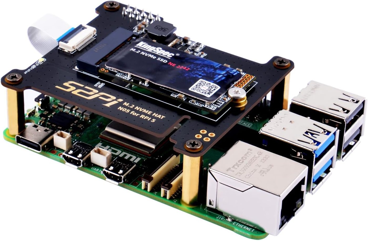
Installation follows the standard M.2 pattern: insert the drive into the Key-M socket at roughly 30 degrees, press it flat once seated, and secure it with the single retention screw the HAT+ ships with. Confirm no gap at the connector edge before tightening. The drive has no power switch of its own — it powers up and down with the system. Volume 3 §2.1 covers the 2230-versus-2242 form-factor decision in detail; this volume assumes that choice is already made.
6.4.3 Connect the HAT+ FFC cable
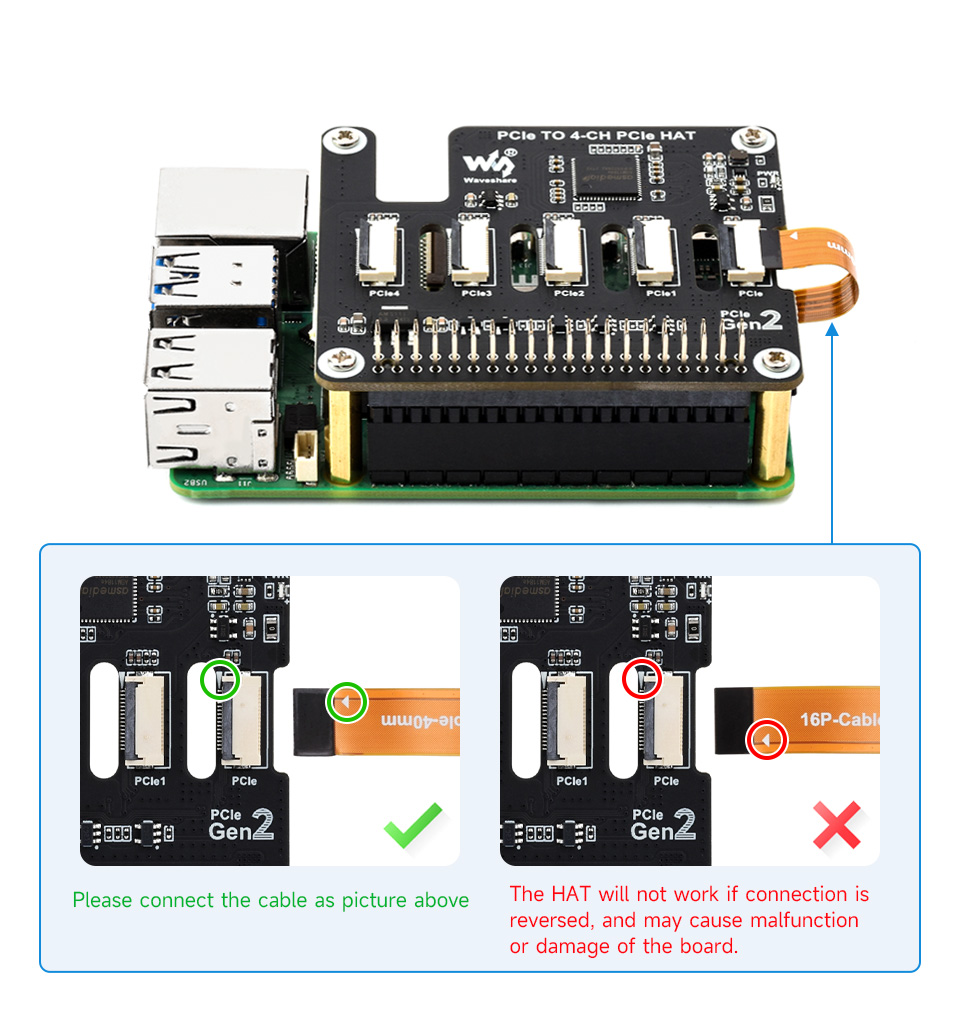
This step has a directly sourced warning behind it, even though the board pictured (a Waveshare 4-channel PCIe HAT+) differs from the PiFlux’s own M.2 Mod. Waveshare’s documentation for this HAT+ family states plainly that a reversed FFC connection “will not work” and “may cause malfunction or damage of the board” — open the locking tab fully, insert the cable in the orientation the board’s silkscreen shows, close the tab, and confirm the run is straight rather than kinked. A kinked FFC cable is the single most common installation error on this class of interface, independent of any PiFlux-specific documentation.
6.5 Step 4 — Install the Radio Module
6.5.1 Placement and connection (Base Radio)
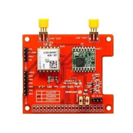
The Base Radio is a combined GPS-plus-LoRa HAT carrying two independent SMA antenna connectors — one for GPS, one for LoRa — with the LoRa side typically offering a jumper-selectable operating band (433, 868, or 915 MHz on a representative reference board). Inside the PiFlux, these leads route to the antenna mounts labeled “GPS” and “LoRa” on the chassis exterior (§9, Figure 6.14) rather than terminating internally. The Pi-side interface for a HAT of this class is ordinarily UART for the GPS module’s NMEA output and SPI for the LoRa transceiver — the conventional split for this hardware combination generally — but Carbon Computers has not published the PiFlux’s specific overlay or driver requirement, and that detail is [VERIFY from Carbon Computers support or the board’s own silkscreen/datasheet] rather than assumed here.
6.5.2 Advanced Radio additional step: SDR antenna connector
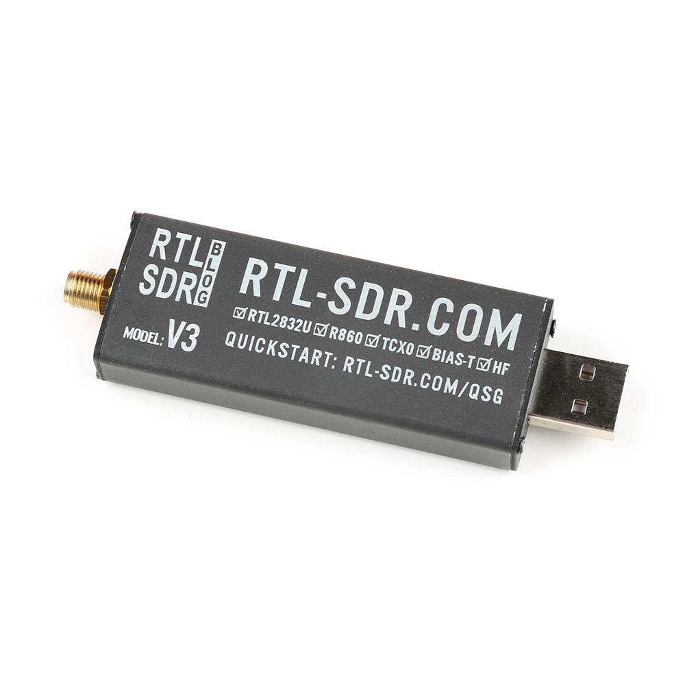
This is the one genuine ambiguity the original series brief flagged as a critical gap, and it has a reasonably confident answer: Carbon Computers’ product description lists “optional internal GPS, WiFi (external antenna), and LoRa installation, and external USB SDR dongle” as the add-on set — language identifying the Advanced Radio’s SDR capability as a USB-connected receiver dongle (an RTL-SDR-class device, consistent with the reference part pictured), not an onboard tuner or a bare SMA pass-through wired into a custom board. On that reading, “installing” the SDR path beyond the Base Radio’s GPS+LoRa hardware is mostly a matter of routing an accessible internal USB port to the dongle and deciding whether its own small antenna stays internal or is extended to an external mount. Carbon Computers does not specify a bundled dongle model, USB port location, or SMA extension — all three remain [VERIFY]. Volume 8 covers the SDR software stack and band coverage once the dongle is in place.
6.6 Step 5 — Install the External WiFi Mod
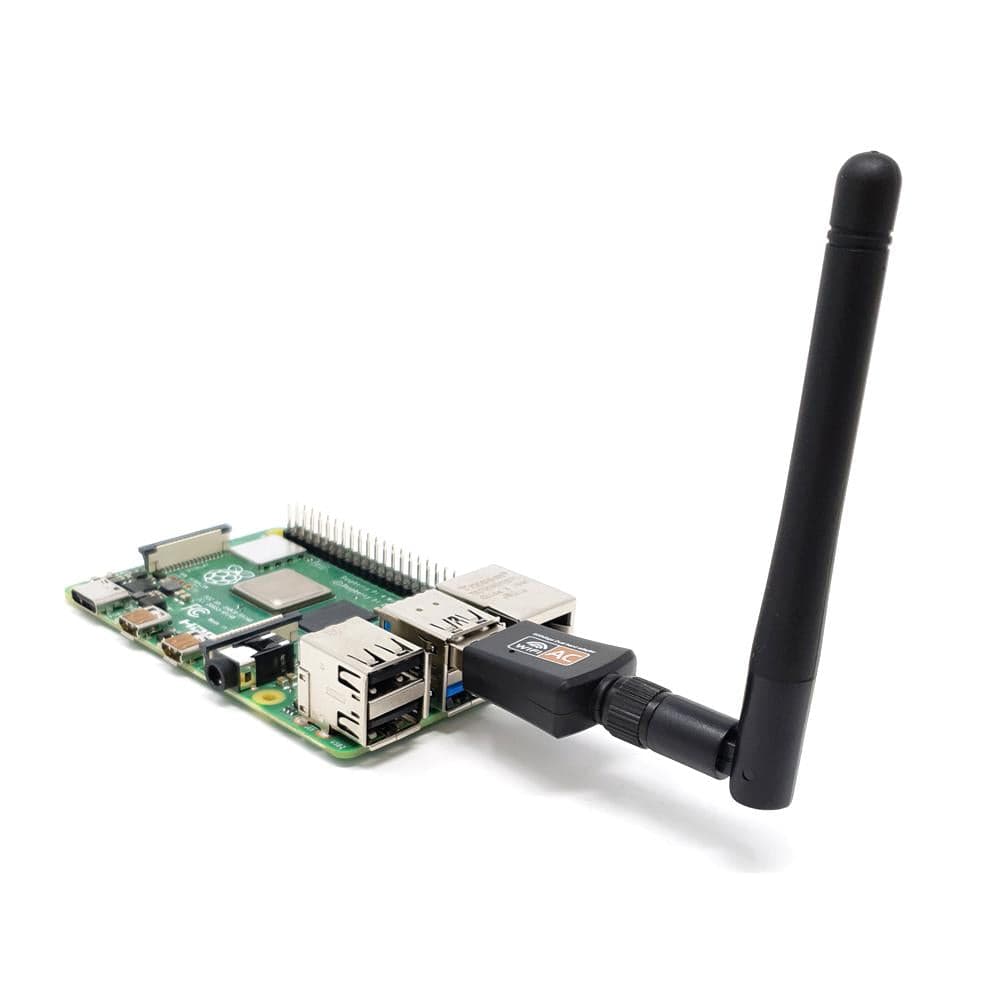
Carbon Computers’ product description groups the External WiFi Mod with the radio add-ons as “internal … WiFi (external antenna)” — an internally mounted USB WiFi adapter whose antenna pigtail routes to an external SMA mount, rather than a self-contained dongle poking out with its own stub antenna. That mount is directly visible and labeled “PI WIFI” on the assembled-unit photograph (Figure 6.14, §9), distinct from the Pi 5’s onboard 802.11ac radio. The specific chipset is not published; whether it needs an out-of-tree driver on any of the six supported OSes is the same question Volume 7 §6 already flags as [VERIFY] per distribution — an OS-configuration matter for that volume, not an assembly step.
6.7 Step 6 — Install the Active Cooling System
6.7.1 Mounting the fan or heatsink assembly
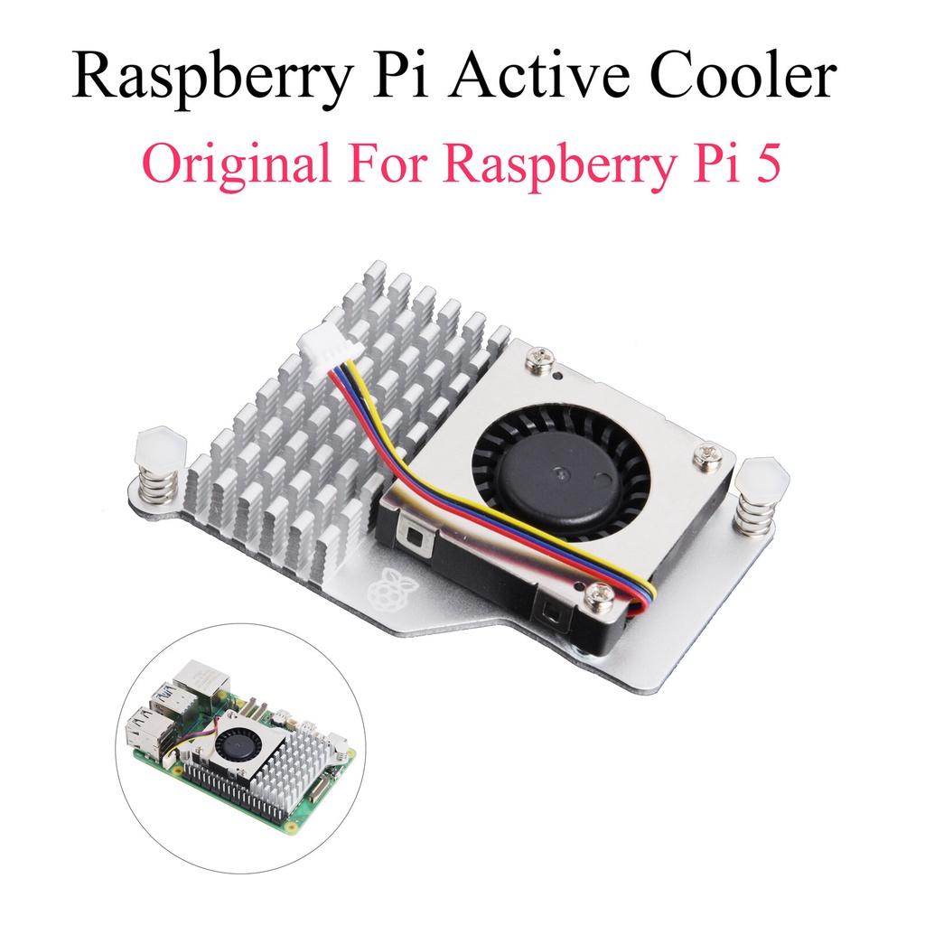
This section carries a genuine tension worth stating rather than papering over. The r.1 Build Guide’s own base BOM already includes a “Pi 5 cooler,” and every photograph of the assembled Pi 5 subassembly shows an active part — finned heatsink, small blower fan on top, mounted to the board’s four stock holes with spring-loaded screws, installed before the display is ever attached — functionally the same class of hardware pictured in Figure 6.11. Volume 1 and Volume 5, meanwhile, list an “Active Cooling System” as a separate catalog add-on with its own unconfirmed price. Nothing retrieved for this volume resolves whether that catalog line is the same stock cooler offered separately for a barebones/DIY buyer, or a distinct, higher-capacity solution layered on top of the one already fitted — flagged [VERIFY directly with Carbon Computers] rather than guessed at.
Whichever it is, the mechanical installation is the same: retention screws into the Pi 5’s stock mounting holes, heatsink over the SoC on a factory-applied thermal pad. The one documented fitment issue is specific: per the r.1 guide, “depending on the cooler you may have to modify the cooling fins to fit the power cable and USB-C adapter” that route past it — the guide names the Argon blow cooler as needing no modification, implying others may need fin trimming. A second, larger cooler layered on top should expect the same problem, likely worse.
6.7.2 Fan header connection
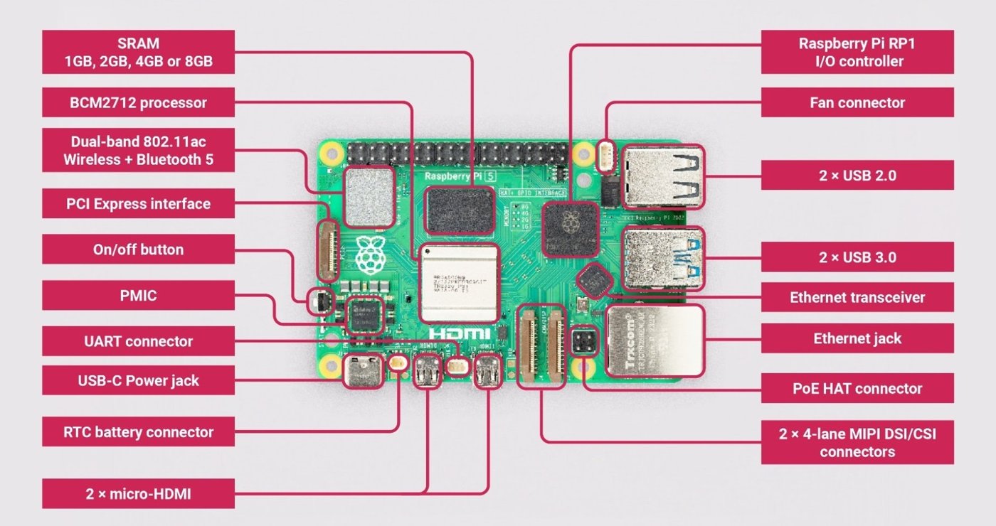
The Pi 5 carries a dedicated 4-pin fan connector next to its USB-C power jack, keyed so the connector only seats one way. Raspberry Pi OS drives this header automatically through its thermal governor once a fan is connected — no manual configuration is required for the default behavior, and Volume 4 §5 covers the governor and thermal-tuning options in depth for a reader who wants to change the default fan curve.
6.8 Step 7 — Insert the microSD and First Boot
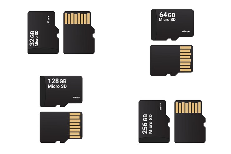
The r.1 guide’s own first-boot procedure is concrete and worth quoting closely. Flash the microSD with Raspberry Pi Imager, then edit /boot/config.txt and append the following lines before first boot:
dtoverlay=vc4-kms-v3d
#DSI1 Use
dtoverlay=vc4-kms-dsi-waveshare-panel-v2,5_0_inch_a
#DSI0 Use
The DSI1 line is active by default; the commented DSI0 variant is for a build using the Pi 5’s other DSI connector. With the card imaged, insert it into the microSD slot — reached through the extender fitted in §2, so day-to-day OS swaps (Volume 7 §3) never require reopening the case — and power on via the top pull-switch mechanism (press to turn on; pull the attached key ring to turn off, per the label visible in Figure 6.4).
Display rotation is the one remaining first-boot task, and it varies by OS: the guide’s generic path is to locate the DSI output under display settings and set orientation to Left. For Kali specifically, Carbon Computers publishes exact commands, reproduced here as the one OS with this level of documented detail:
- Pre-boot — edit
/boot/config.txtand add the samedtoverlay=vc4-kms-v3danddtoverlay=vc4-kms-dsi-waveshare-panel-v2,5_0_inch_alines shown above. - Boot and login screen — append
fbcon=rotate:3to/boot/cmdline.txtso the console framebuffer isn’t sideways at boot. In/etc/lightdm/lightdm.conf, under[Seat:*], adddisplay-setup-script=xrandr --output DSI-2 --rotate left, and create/etc/lightdm/setup.shwith the samexrandrline. - Desktop and touch input — under Settings → Display, manually set rotation to Left (the desktop session doesn’t inherit the boot-time rotation). Remap touch coordinates by creating
/etc/udev/rules.d/99-waveshare-touch.ruleswithENV{ID_INPUT_TOUCHSCREEN}=="1", ENV{LIBINPUT_CALIBRATION_MATRIX}="0 -1 1 1 0 0".
Volume 7 covers the remaining five OSes at the level it already establishes; Kali is simply the one distribution with published exact commands rather than the general “varies per OS” guidance given for the rest. For an add-on-equipped build, lsblk (NVMe), iwconfig/nmcli (second WiFi interface), gpsd/cgps (GPS fix), and lsusb (SDR dongle) still apply as verification, but none come from a Carbon Computers-published checklist — Section 11 assembles them as this volume’s own synthesis.
6.9 Antenna Mounting and Routing
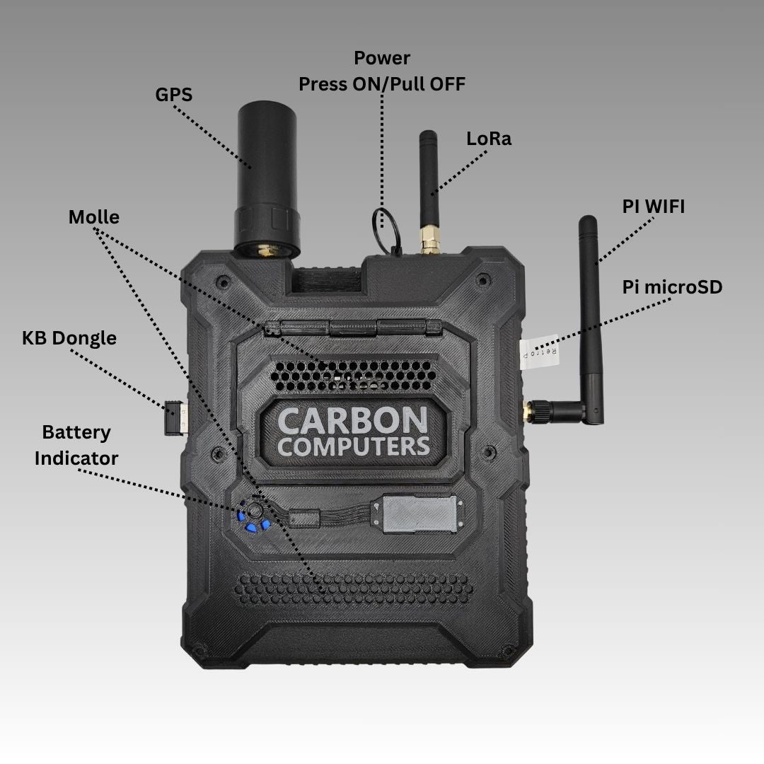
Carbon Computers’ own labeled photograph of the assembled unit (Figure 6.14) is the clearest source on external routing, and resolves most of what the original brief flagged as unconfirmed. Reading the labels: a GPS antenna sits in a substantial cylindrical mount at top-left — larger than a simple whip, consistent with a patch or helical antenna rather than a bare monopole. The top pull power switch (§8) sits top-center, its key ring looped through it. A LoRa whip antenna on SMA sits just right of that. Further right, a second whip antenna on its own SMA mount is labeled “PI WIFI” — the External WiFi Mod’s antenna connector, distinct from the Pi 5’s onboard radio. “Pi microSD” labels the externally accessible card slot the extender (§2) routes to. The opposite edge carries a “KB Dongle” port and a bank of “Battery Indicator” LEDs, with a “Molle” panel occupying the rear-face center.
Notably absent is any dedicated antenna mount for the Advanced Radio’s SDR path — consistent with §5.2’s finding that the SDR capability is a USB dongle rather than a chassis-integrated radio: whatever antenna the dongle carries most likely stays external on its own rather than routing through a dedicated port. Whether Carbon Computers provides an SMA pass-through for mounting an SDR antenna flush with the GPS/LoRa/WiFi cluster is [VERIFY] — no source shows one.
Keeping the LoRa and WiFi leads dressed apart from each other and from the GPS lead inside a chassis this tight is sound RF practice, reducing the chance of one radio desensitizing another’s receive path — a general recommendation this volume is making, not a documented Carbon Computers instruction.
6.10 Known Fitment Gotchas
Drawn directly from the r.1 Build Guide’s cautionary notes, plus one inference-based gotcha for the undocumented add-on steps:
- FPC video cable length. The short cable is a tight fit but works; the long one routes more easily but must be taped in place, or it works loose over time (§3.2).
- Cooler-to-adapter clearance. Some Pi 5 coolers need fin trimming to clear the power cable and USB-C adapter; the Argon blow cooler needs no modification (§7.1).
- Tight-fit insertion. The Pi 5/display subassembly fits into the chassis at an angle, and the right-side USB port opening may need “priming” — widened slightly by hand. Keep the FPC video cable and any other wiring clear of pinching; the guide repeats this warning twice (§3.2).
- Battery wire pinch at the front face. Move the battery’s power lead up and clear before the keyboard support frame and front face come together, or the frame pinches it (§3.2).
- Back-attachment screw holes are covered, not missing. The four holes for the optional rear panel are covered by a thin printed plastic layer; pierce it before driving the M2×4 mm screws (§2).
- Screw torque. Snug only — don’t overtighten — and functionally test (especially the pull-switch) before final closure, not after (§2).
- Add-on chassis clearance is unconfirmed. No source documents chassis-specific fitment for the M.2 Mod, either Radio, or the External WiFi Mod — expect the same cooler-clearance problem, likely compounded, wherever these boards stack. Confirming with Carbon Computers support before final assembly is the safer path for a DIY build carrying all four add-ons.
6.11 Post-Assembly Verification
This combines the one verification sequence Carbon Computers actually publishes (display rotation and touch calibration, §8) with a broader set this volume assembles from the add-on interfaces documented elsewhere in the series. Only the first two items below are confirmed Carbon Computers guidance; the rest are this volume’s own synthesis, not a published checklist.
- Power-on and desktop reached. Confirm the unit powers on via the top pull switch and reaches the desktop.
- Display rotation and touch tracking correct. Boot splash, login, and desktop all oriented correctly; touch tracks the finger rather than an inverted/rotated axis — per §8.
- NVMe enumerated (if M.2 Mod installed).
lsblkshows the NVMe device. - Both WiFi interfaces present (if External WiFi Mod installed).
iwconfigornmcli deviceshows the Pi 5’s onboard radio and the Mod’s adapter both enumerating. - GPS fix (if Base/Advanced Radio installed).
gpsdrunning andcgps(or equivalent) reports a fix, ideally with a clear sky view. - LoRa interface present (if Base/Advanced Radio installed). The transceiver enumerates on its expected interface — the exact device path isn’t standardized across the sources available here.
- SDR dongle recognized (if Advanced Radio installed).
lsusbshows the dongle; Volume 8 covers the software stack from there. - No thermal throttling at idle.
vcgencmd get_throttledreturns0x0after several idle minutes — Volume 4 §4 covers what a nonzero result means.
Every unit Carbon Computers assembles itself is, per the product page, “assembled, tested, and configured before shipment” — this checklist is for the builder doing that work themselves.
6.12 Resources
Table 2 — 12. Resources
| Resource | URL |
|---|---|
| PiFlux build video | https://youtu.be/YwcIiGrZ_AY |
| Pi Flux r.1 Build Guide (PDF, primary source for Sections 2, 3, and 8) | https://cdn.shopify.com/s/files/1/0563/8687/9591/files/Pi_Flux_r1_-_Build_Guide.pdf |
| Pi Flux — Build Guide & Keyboard Functions (Carbon Computers blog) | https://carboncomputers.us/blogs/news/pi-flux-build-guide-keyboard-functions |
| Pi Flux — Display Configuration (Carbon Computers blog) | https://carboncomputers.us/blogs/news/pi-flux-display-configuration |
| Kali on your Pi Flux (Carbon Computers blog) | https://carboncomputers.us/blogs/news/kali-on-your-pi-flux |
| Carbon Computers product page | https://carboncomputers.us/products/pi-flux |
| Carbon Computers support (Discord, email, phone) | https://discord.gg/dpdZ6ybw · [email protected] · 786-505-3830 |
| Vol 3 — M.2 Storage | ../../PiFlux/02-inputs/volume_sources/vol3.md |
| Vol 4 — Power & Thermal | ../../PiFlux/02-inputs/volume_sources/vol4.md |
| Vol 5 — The Add-On Catalog | ../../PiFlux/02-inputs/volume_sources/vol5.md |
| Vol 7 — OS Options & Multiboot | ../../PiFlux/02-inputs/volume_sources/vol7.md |
| Vol 8 — SDR Capabilities | ../../PiFlux/02-inputs/volume_sources/vol8.md |
Comments (0)