PiFlux · Volume 3
M.2 Storage
The M.2 Mod / HAT+, NVMe selection for the PiFlux chassis, boot-from-NVMe setup, and SD vs. NVMe
3.1 The M.2 Mod: What It Is
3.1.1 The Pi 5 PCIe path and HAT+
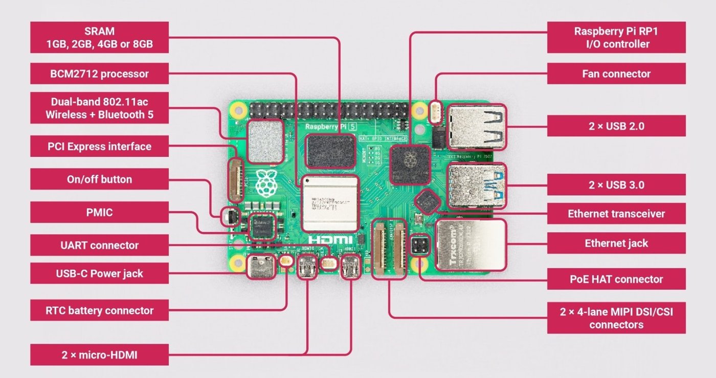
The Raspberry Pi 5’s BCM2712 SoC exposes two separate PCIe interfaces: a ×4 link that connects internally to the companion RP1 I/O controller (which handles the Pi 5’s USB, Ethernet, and GPIO — the chip Volume 2 introduces for RAM and compute selection), and a second, independent ×1 PCIe 2.0 lane (5 GT/s line rate) routed directly from the SoC to an external connector on the underside of the board. That second, dedicated lane — not RP1’s — is what the M.2 interface uses. It is brought out on a flat FFC (Flexible Flat Cable) connector rather than to an on-board M.2 socket, which is the detail that makes the M.2 Mod necessary at all: on a Compute Module 4 carrier board the designer can wire an M.2 socket directly to the CM4’s PCIe pins; on the Pi 5 the external PCIe lane is present but unterminated until something — the official M.2 HAT+, or the PiFlux M.2 Mod — plugs into the FFC connector and terminates it in an M.2 Key M socket.
A single PCIe 2.0 lane is a real but modest allocation of bandwidth, and it is the single most important fact governing everything else in this volume: whatever NVMe drive the builder installs, the Pi 5’s own interface — not the drive — sets the ceiling. Section 2.2 works through what that ceiling means in practice.
3.1.2 The M.2 Mod hardware
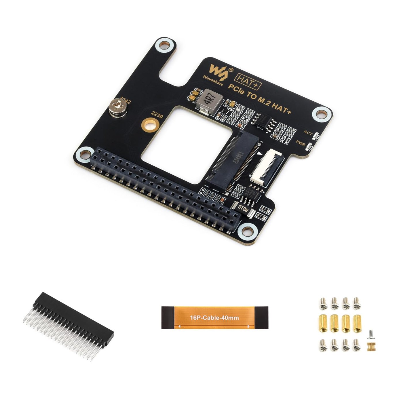
Raspberry Pi’s own first-party accessory for this job is the M.2 HAT+ — a small PCB carrying an FFC cable, an M.2 Key M socket, and mounting standoffs that bolt to the Pi 5’s existing mounting holes. It ships in two variants: the standard M.2 HAT+, which accepts 2230 or 2242 drives, and the M.2 HAT+ Compact, a lower-profile board that accepts 2230 only. Both are HAT+-compliant, meaning a Pi 5 running current firmware recognizes the board and enables the external PCIe port automatically, with no manual config.txt edit required.
Carbon Computers sells the M.2 Mod as a $59 add-on for the PiFlux — “can be bundled with your Flux purchase to be installed by us,” in the product page’s own wording — but the page stops there. It does not state whether the M.2 Mod is the official Raspberry Pi M.2 HAT+ (or M.2 HAT+ Compact) fitted into the PiFlux chassis, a licensed variant of that reference design, or a fully custom Carbon Computers board built to a different physical layout. This is a genuine gap rather than a detail this volume will paper over: whether the M.2 Mod is the official HAT+ family or a proprietary board remains [VERIFY directly against Carbon Computers support or the physical unit], and it matters, because it determines two things downstream — which drive form factors physically fit, and whether the PCIe port enables itself automatically or needs a manual dtparam=pciex1-style config change (Section 4.1).
What can be said with reasonable confidence, short of that confirmation: any board doing this job — official or third-party — is built around the same physical primitives as the HAT+ reference design, because there is no other way to route a Pi 5’s external PCIe lane to an M.2 socket. An FFC cable from the Pi 5’s board-edge connector, a small PCB with the Key M socket and its PCIe pinout, and a set of standoffs sized to hold the card at the right height above the Pi board are the load-bearing pieces regardless of who manufactures them. The PiFlux M.2 Mod’s exact PCB dimensions, mounting depth inside the chassis, and any thermal pad or heatsink clearance note are not published on the product page and remain [VERIFY against Carbon Computers documentation or the physical unit] — a builder installing an M.2 Mod should confirm clearance for the specific drive length before ordering, rather than assume it from the HAT+ family’s published dimensions.
3.2 NVMe Selection
3.2.1 Form factor: 2230 vs. 2242
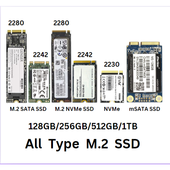
M.2 form-factor numbers encode physical dimensions in millimeters: width first, then length. M.2 2230 is 22 mm wide by 30 mm long — the shortest common NVMe card, found in ultrabooks, handhelds, and the Steam Deck’s aftermarket upgrade market. M.2 2242 is the same 22 mm width at 42 mm long — a less common size, but still a standard NVMe card length rather than an exotic one. M.2 2280 — 22 × 80 mm — is the size most desktop and DIY-PC builders default to, since it is the most common retail NVMe card, but it is also the longest of the three and the one most likely to run into chassis clearance limits on a small carrier board.
Raspberry Pi’s own M.2 HAT+ documentation confirms the standard HAT+ accepts 2230 or 2242 drives, and the Compact variant accepts 2230 only — neither official board supports 2280. If the PiFlux M.2 Mod follows the same physical architecture as the HAT+ family, as its size and function suggest it must, then 2280 drives will not fit the PiFlux chassis either. This deep-dive treats that as the working assumption rather than a confirmed spec, since Carbon Computers does not publish a compatibility list for the M.2 Mod specifically [VERIFY against Carbon Computers before ordering a drive]. Builders should default to sourcing a 2230 or 2242 drive and confirm fitment before committing to a longer card.
Practically, 2230 is the easier form factor to source today: it’s the size used across laptop OEM upgrades and the handheld-gaming aftermarket, so drives at this length are stocked by mainstream retailers in a wide range of capacities. 2242 is a narrower market — fewer models, and prices per gigabyte are often less competitive than 2230 or 2280 — but still a real, purchasable category rather than a niche one.
3.2.2 Performance tiers on PCIe 2.0 ×1
The Pi 5’s single-lane PCIe 2.0 interface has a documented peak transfer rate of roughly 500 MB/s. That figure describes the 5 GT/s line rate after PCIe 2.0’s 8b/10b line encoding overhead is accounted for — it is the ceiling the interface itself imposes, independent of what drive is plugged in. Independent benchmarks of Pi 5 M.2 HAT+ setups (Pimoroni’s NVMe Base among them) consistently land sequential-read throughput in the roughly 400–450 MB/s range in practice — comfortably under the 500 MB/s peak, as is typical once real-world overhead is included, but nowhere near what a modern NVMe drive is rated for on its native interface.
That gap is the single most important buying insight in this section: essentially every NVMe SSD sold today, including budget drives, is a PCIe 3.0 or PCIe 4.0 ×4 part. The WD SN740, for example, is rated for roughly 5,150/4,850 MB/s sequential read/write on a PCIe 4.0 ×4 host — more than ten times what the Pi 5’s single Gen 2 lane can carry. A Sabrent Rocket 2242 in its PCIe 3.0 form is rated around 2,500/2,100 MB/s; even that “slower” Gen 3 drive still runs at roughly five times the Pi 5’s interface ceiling. On the PiFlux, both drives will benchmark identically at whatever the PCIe 2.0 ×1 link permits, because the interface — not the flash, not the controller — is doing the limiting. A $30–$50 entry-tier NVMe drive and a $150 flagship will perform the same on this platform.
Random small-block I/O — the pattern that governs how snappy an OS feels booting and launching applications, as opposed to how fast a single large file copies — matters more for a boot drive than sequential bandwidth in the abstract. But the same interface ceiling that caps sequential throughput also caps how much random I/O can move across the bus at once, so this volume will not assert a specific 4 kB random-IOPS figure for any drive on the PiFlux — that number hasn’t been benchmarked here, and the manufacturer’s own random-IOPS ratings (measured on a full PCIe 3.0/4.0 ×4 host) don’t transfer cleanly to a single Gen 2 lane. The practical guidance stands regardless: given the interface bottleneck, there is little to be gained by chasing a “faster” drive on paper, and the meaningful selection criteria shift to form factor, endurance (Section 2.3), and price.
3.2.3 Endurance and write-cycle considerations
NVMe endurance is rated in TBW — total terabytes written over the drive’s warrantied life — and TBW scales with capacity: a manufacturer’s larger-capacity SKU in a given line typically carries a proportionally higher TBW rating than its smaller sibling, since more NAND die means more total write budget. Published figures for drives in the 2230/2242 category range widely by capacity and model — for instance, WD’s SN740 line is rated up to roughly 500 TBW at its higher capacities, and Sabrent’s Rocket 2242 line publishes TBW figures as high as roughly 1,710 TBW at its largest capacity point. These numbers are illustrative of the category rather than a promise for any specific capacity a builder buys; the exact TBW for the capacity actually purchased should be checked against that model’s datasheet, since it varies within a single product line.
Set against that endurance budget, a PiFlux running as a field Linux daily driver — OS updates, application installs, log writes, document editing — writes a modest volume of data over a year: tens of gigabytes is a realistic order of magnitude for this workload, not the hundreds of terabytes that would meaningfully draw down even an entry-level drive’s TBW allowance. Practically, TLC NAND — the mainstream flash type used across nearly all consumer NVMe drives today, including every drive named in this volume — is fully adequate at this endurance level. There is no case for seeking out MLC- or SLC-class drives (rarer, pricier, and increasingly hard to find in the 2230/2242 category at all) for a PiFlux boot drive; the write-endurance headroom on a standard TLC drive vastly exceeds what this use case will ever consume.
3.2.4 Recommended drives
Two real, currently available drives illustrate the category the PiFlux M.2 Mod is built around. The Western Digital SN740 ships in the 2230 form factor across capacities from 256 GB to 2 TB, on a PCIe 4.0 ×4 interface — again, far beyond what the Pi 5’s single Gen 2 lane will exploit, which is exactly the point made in Section 2.2. The Sabrent Rocket 2242 (and its lower-power Rocket Nano 2242 sibling) ships in the 2242 form factor across similarly wide capacity options, on either a PCIe 3.0 or PCIe 4.0 ×4 interface depending on the specific SKU.
Naming these two drives is meant to orient a builder toward the right category — small-form-factor NVMe SSDs from established manufacturers, sold through mainstream retail channels — rather than to endorse a specific model as the compatible drive for the PiFlux. Two things remain outside what this volume can confirm: current pricing and in-stock availability change continuously in this market and should be checked at the time of purchase, and Carbon Computers does not publish a tested compatibility list for the M.2 Mod, so a builder buying either drive (or any other 2230/2242 NVMe SSD) is relying on the general M.2 Key M electrical and mechanical standard rather than a manufacturer-confirmed pairing. Given the interface bottleneck established in Section 2.2, the buying decision for a PiFlux realistically comes down to form factor fit, capacity for the intended OS/data footprint, and price — not sequential-throughput specification sheets that the platform cannot fully exploit.
3.3 SD vs. NVMe: Decision Framework
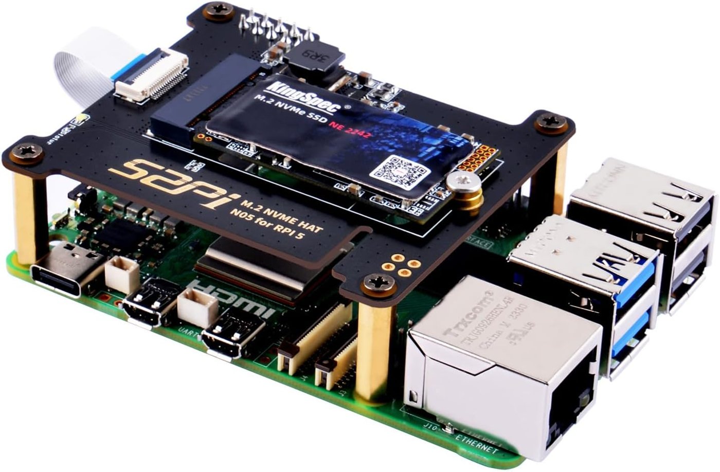
The PiFlux’s native storage — microSD, swappable in seconds — is the device’s signature convenience feature (Volume 1, Volume 7), and for many use cases it is entirely sufficient. The decision to add the $59 M.2 Mod and a drive on top of it comes down to four factors.
Boot and application-launch responsiveness. NVMe over even a single PCIe 2.0 lane meaningfully outperforms a microSD card’s UHS interface, and the difference is the kind a user notices in daily use — faster boot, faster application launch, less waiting on the touchscreen after a cold start. This volume will not put a specific percentage figure on that improvement, since the actual margin depends heavily on which SD card is being compared against which NVMe drive, and no controlled measurement on PiFlux hardware backs a number here; the qualitative direction, however, is well established across the Pi 5 NVMe-boot community generally.
Sustained write endurance. microSD cards, even good ones, wear under sustained write workloads in a way that NVMe drives — with meaningfully higher TBW ratings at comparable price points (Section 2.3) — tolerate more comfortably. A PiFlux used as a daily-driver Linux terminal with frequent writes (logging, package installs, active document work) puts less long-term wear risk on an NVMe drive than on the SD card carrying the same workload.
Random I/O and multitasking feel. The Pi 5’s RP1-mediated PCIe path gives an NVMe drive an advantage in random small-block access patterns relative to SD — the kind of access pattern that governs how a desktop environment feels under concurrent application use, distinct from raw sequential throughput (Section 2.2).
The dual-boot enabler. Perhaps the most PiFlux-specific reason to add NVMe: once an OS lives on the NVMe drive, the microSD slot is freed for its native purpose — instant OS swap — without disturbing the primary installation. A builder can run a daily-driver OS from NVMe and keep a security-focused distribution (Kali, Parrot) on a swappable SD card, moving between the two without reinstalling either. Volume 7 covers this multiboot strategy in full; Section 5 below sketches the layout.
Set against those four factors, the case for staying on SD-only is straightforward: lower cost (no $59 Mod, no drive purchase), and adequate performance for lighter workflows — casual browsing, single-application terminal use, or a PiFlux kept mostly for its radio add-ons rather than as a general-purpose Linux desktop. Volume 1’s RAM-tier guidance (Volume 2) and this section’s storage guidance track the same underlying logic: heavier, more concurrent daily use justifies more of the PiFlux’s optional add-on budget.
3.4 Boot-from-NVMe Setup
3.4.1 Bootloader configuration
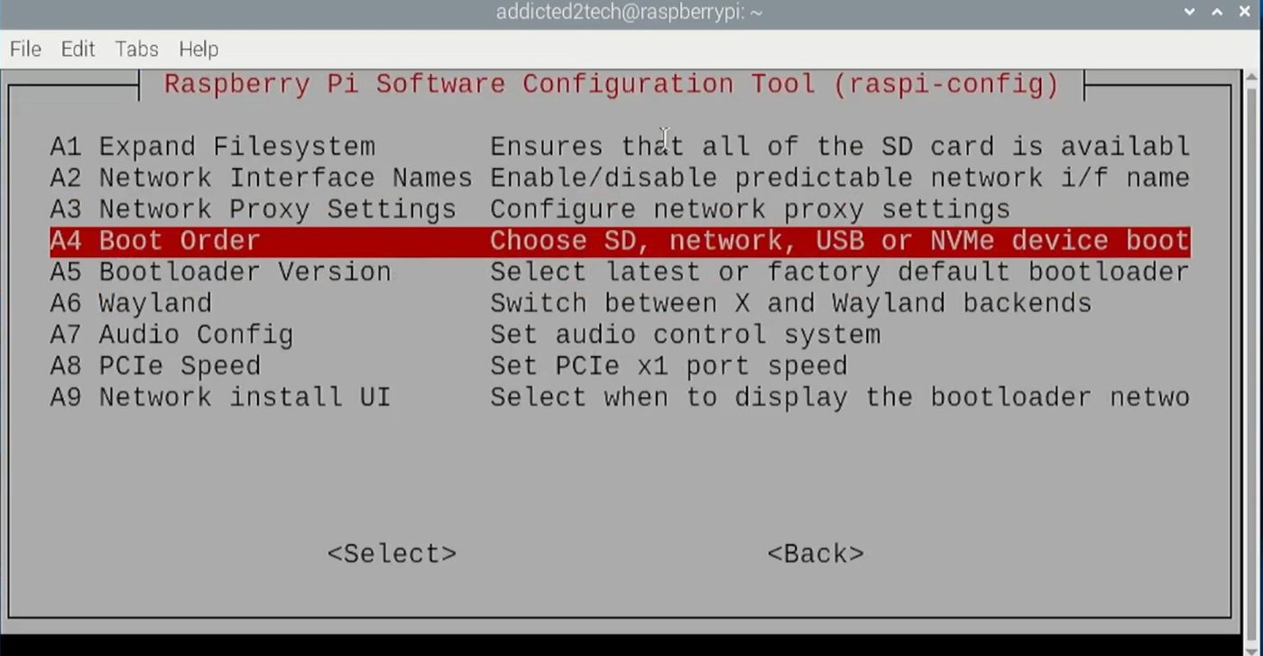
The Raspberry Pi 5 boots under control of its EEPROM bootloader, and the device search order that bootloader follows is governed by the BOOT_ORDER setting. Two paths reach the same setting. The simple one is raspi-config → Advanced Options → Boot Order, which presents an “NVMe/USB Boot” option that puts external storage ahead of the SD card without the builder needing to know the underlying encoding. The direct path is sudo rpi-eeprom-config --edit, which opens the EEPROM’s configuration text for editing, including the BOOT_ORDER line itself.
BOOT_ORDER is a hexadecimal value in which each digit is a device code, and the digits are read right to left as the attempt sequence: 1 is the SD card, 4 is USB mass storage, 6 is NVMe, and f means “go back to the start of the sequence if every device so far has failed to boot.” A BOOT_ORDER of 0xf416, for example, reads right to left as NVMe first, then SD, then USB, then restart the sequence if all three fail — an NVMe-first configuration. This digit encoding is consistent across Raspberry Pi community documentation and forum guidance describing the Pi 5’s bootloader, though this volume did not locate a single directly quotable line from Raspberry Pi’s own reference pages spelling out the right-to-left read order in those exact terms — treat the specific hex value used [as VERIFY against the current rpi-eeprom-config output on the actual unit] rather than copying 0xf416 blind, since EEPROM releases have adjusted default values over time.
Two prerequisites matter before any of this works. First, the Pi 5’s EEPROM firmware must be current enough to support NVMe boot at all — firmware from the Pi 5’s early release window (late 2023) may predate reliable NVMe boot support, which landed via EEPROM updates over late 2023 into early 2024, so sudo rpi-eeprom-update (and a reboot) may be a required first step on an older unit. Second, if the M.2 Mod is HAT+-compliant — meaning it identifies itself to the Pi 5 the way the official M.2 HAT+ does — the external PCIe port enables itself automatically with no config.txt change needed. If the M.2 Mod turns out to be a non-compliant custom board (Section 1.2’s open question), a manual dtparam=pciex1-style entry in config.txt may be necessary to bring the PCIe port up before the drive is even visible to the OS — worth checking with lspci before troubleshooting boot order at all.
3.4.2 Flashing the NVMe
Two practical approaches get an OS image onto the NVMe drive. The first: flash the drive before installing it in the PiFlux, using a USB-to-M.2 enclosure on another computer and the Raspberry Pi Imager (or dd) exactly as one would flash a microSD card. This is the cleaner approach when a USB-to-M.2 adapter matching the drive’s form factor is already on hand, since it avoids any dependency on the PiFlux itself being bootable during the process.
The second: flash the NVMe from the PiFlux itself, booting from the existing microSD card and writing the target OS image to the NVMe device node (typically /dev/nvme0n1) using dd, Raspberry Pi Imager pointed at the NVMe target, or rpi-clone to duplicate an already-configured SD installation across. This is the typical path for a PiFlux builder, since it requires no additional hardware beyond the M.2 Mod and drive already installed — the Pi boots normally from SD, writes the NVMe drive as a target disk, and only then is the boot order changed to prefer it.
3.4.3 First boot and verification
After the boot order is updated to prefer NVMe and the Pi reboots, several checks confirm the drive is actually the one in use rather than a fallback to SD. lsblk should list the NVMe device (nvme0n1) alongside its partitions; df -h should show the root filesystem mounted from an NVMe partition rather than an mmcblk0 (SD card) device; and cat /proc/cmdline should show a root= parameter pointing at the NVMe partition’s UUID or device path rather than the SD card’s. dmesg | grep -i pcie (or nvme) should show the kernel enumerating the PCIe device and NVMe controller during boot — confirmation that the FFC connector, the M.2 Mod, and the drive are all electrically sound and recognized, not just that some root filesystem happens to be mounted.
3.5 NVMe + SD Dual-Storage Layout
The combination this volume recommends for a PiFlux with the M.2 Mod installed: NVMe carries the primary, daily-driver OS — Raspberry Pi OS or whichever general-purpose distribution the builder runs most — configured to boot first via the BOOT_ORDER sequence in Section 4.1. The microSD slot is then left free for its native PiFlux role: an instantly swappable alternate OS, such as Kali Linux or Parrot Security OS, that the builder pops in for a specific task without touching the NVMe installation at all.
Because the boot order places NVMe first, the default behavior with nothing in the SD slot is simply to boot the primary OS from NVMe. Inserting an SD card with a bootable alternate OS and rebooting invokes the BOOT_ORDER fallback logic — if the builder wants the SD card to take priority for a session, raspi-config’s Boot Order screen or a manual SD-first BOOT_ORDER edit handles that without disturbing the NVMe drive’s contents. This is a meaningfully more capable multiboot arrangement than SD-only swapping, since the “always available” OS lives on the faster, more durable medium, and the swap card becomes a genuinely optional accessory rather than the single point of failure for the whole device. Volume 7 covers the full multiboot decision framework — including PINN- and BerryBoot-style single-card multiboot as alternatives to this NVMe+SD split — in depth.
3.6 Resources
Table 1 — 6. Resources
| Resource | URL |
|---|---|
| PiFlux M.2 Mod (Carbon Computers) | https://carboncomputers.us/products/pi-flux |
| Raspberry Pi M.2 HAT+ documentation (reference architecture; PiFlux board not confirmed identical) | https://www.raspberrypi.com/documentation/accessories/m2-hat-plus.html |
| Raspberry Pi 5 / bootloader documentation (BOOT_ORDER, EEPROM update) | https://www.raspberrypi.com/documentation/computers/raspberry-pi.html |
| Vol 2 — Choosing the Pi 5 (RAM tiers, PCIe intro) | ../../PiFlux/02-inputs/volume_sources/vol2.md |
| Vol 4 — Power & Thermal (NVMe power budget) | ../../PiFlux/02-inputs/volume_sources/vol4.md |
| Vol 7 — OS Options & Multiboot | ../../PiFlux/02-inputs/volume_sources/vol7.md |
Comments (0)