PiFlux · Volume 4
Power & Thermal with M.2
Power budget for the Pi 5 + NVMe + display, runtime impact on the 10,000 mAh battery, the Active Cooling System, and thermal management
4.1 The PiFlux Power System
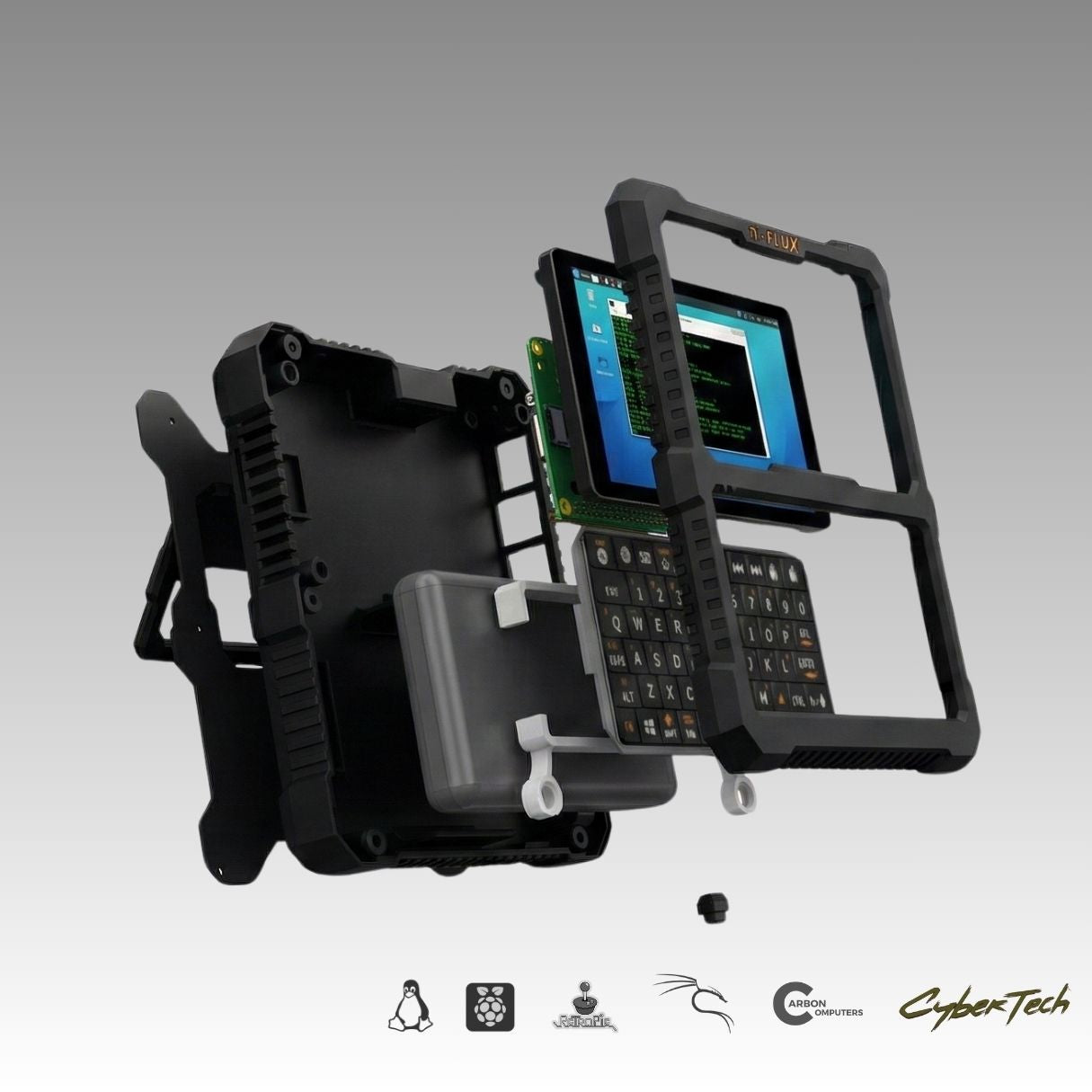
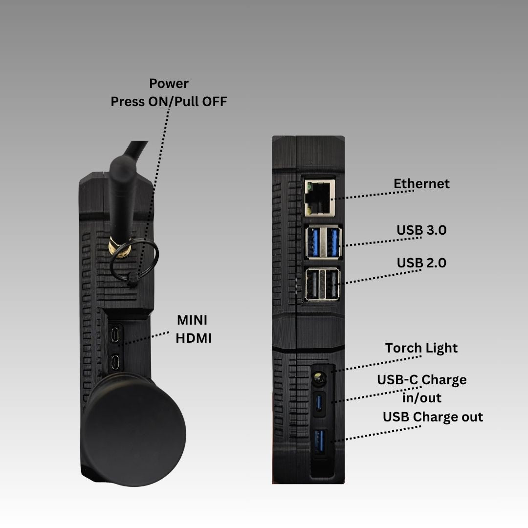
The PiFlux carries its power system inside the chassis rather than as a removable pack: a 10,000 mAh internal battery, seated against the mainboard, feeds the Raspberry Pi 5, the display, the keyboard and its RGB backlight, and — in the full add-on configuration this volume assumes — the M.2 Mod’s NVMe drive, all from the same rail. Carbon Computers publishes the capacity figure and a stated runtime of three to five hours of typical use, but does not publish the pack’s nominal voltage, cell chemistry, or internal charge-management topology on the product page. That gap matters for anyone trying to check the runtime claim against first principles, so this volume states its working assumption plainly rather than treating an unpublished number as settled fact: a 10,000 mAh internal pack in a compact all-in-one chassis of this kind — with no separate battery bay, no removable cartridge, and a single USB-C port doing double duty for charge-in and device charge-out (Figure 4.3) — is most plausibly a single-cell (1S) lithium-ion or LiPo pack at a nominal 3.7 V, with an onboard power-management IC boosting that to the Pi 5’s 5 V rail. That is the same architecture used in the great majority of USB power banks and integrated tablet/handheld batteries at this capacity tier, and it is the assumption this volume carries through its runtime math in §2.4 and §3. It is an engineering inference from the product’s form factor, not a confirmed spec, and a reader who wants certainty rather than a well-reasoned estimate should treat it as [VERIFY against the physical unit or Carbon Computers’ own support documentation].
This volume is the Cyberdecks hub’s platform-authoritative reference on Raspberry Pi 5 power and thermal behaviour — the role Volume 1 (§1, §6) establishes for this series generally. The sibling DFCD deep-dive, which shares the same Pi 5 compute board in a different chassis with a different battery and step-down architecture (an NP-F pack through a Joy-IT buck converter), does not re-derive Pi 5 power and thermal figures independently; its own Volume 5 (§6) cross-references this volume for exactly that material. The workload-tier power figures established in §2.1 below are the same figures the DFCD series adopts, so a reader moving between the two decks’ power volumes will find consistent numbers rather than two independently-estimated sets that happen to disagree.
The M.2 Mod and the radio add-ons (Base Radio, Advanced Radio, External WiFi Mod) all draw from this same 10,000 mAh rail rather than from independent power sources — a detail worth stating up front because it means the full-configuration PiFlux’s real-world runtime is lower than a bare-unit estimate for any add-on combination, not just the M.2 Mod this volume focuses on. Volume 5 covers the radio add-ons’ own power draw in the context of their function; this volume’s job is narrower — quantify what the Pi 5 itself costs across workload tiers, what the M.2 Mod’s NVMe drive adds on top, and what both together mean for the battery this device actually ships with.
4.2 Power Budget
4.2.1 Pi 5 power draw by workload
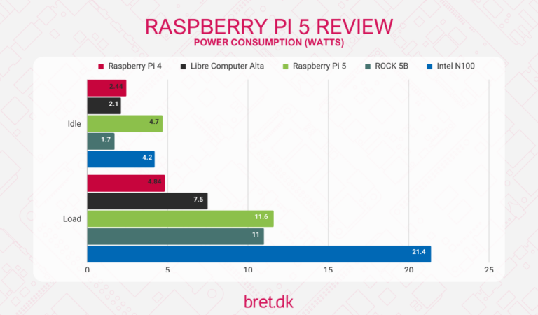
Raspberry Pi does not publish idle- and load-power figures for the Pi 5 on its own product documentation; the company’s published power specification (§2.4 below) covers supply requirements, not measured draw. The figures this volume works from are third-party measurements — specifically raspberry.tips’ 2026 power-consumption benchmark set for the Pi 5, cross-checked against Jeff Geerling’s independent Pi 5 power testing, which is the same pairing of sources the sibling DFCD power volume cites for consistency across the hub. Both report broadly the same shape of result, which is the reason this volume treats the figures as reliable enough to build a runtime estimate on, while still being explicit that neither is a manufacturer number:
Table 1 — Raspberry Pi does not publish idle- and load-power figures for the Pi 5 on its own product documentation; the company's published power specification (§2.4 below) covers supply requirements, not measured draw. The figures this volume works from are third-party measurements — specifically raspberry.tips' 2026 power-consumption benchmark set for the Pi 5, cross-checked against Jeff Geerling's independent Pi 5 power testing, which is the same pairing of sources the sibling DFCD power volume cites for consistency across the hub. Both report broadly the same shape of result, which is the reason this volume treats the figures as reliable enough to build a runtime estimate on, while still being explicit that neither is a manufacturer number
| Workload | Pi 5 draw | Source basis |
|---|---|---|
| Idle, headless (WLAN only) | ~2.7–3.0 W | raspberry.tips 2026 benchmark set |
| Idle, with Ethernet + WLAN + USB + HDMI active | ~3.0–3.6 W | raspberry.tips 2026 benchmark set |
| Moderate desktop use / HD video playback | ~5.7–6.8 W | raspberry.tips 2026 benchmark set |
| CPU-saturating load (stress test, all 4 cores) | ~8.8 W | raspberry.tips 2026 benchmark set; consistent with Geerling’s own stress-test figures |
| Extreme combined load (CPU + USB-SSD I/O + 4K video) | up to ~16 W | raspberry.tips 2026 benchmark set |
The idle figure moves with the peripherals actually active — a headless board on WLAN alone sits toward the bottom of that band, while a board driving HDMI output, Ethernet, and USB peripherals simultaneously sits toward the top, which is the relevant comparison for a PiFlux running its own integrated display and keyboard rather than a bare board on a bench. The moderate-load figure covers the kind of desktop use a field session on the PiFlux is likely to spend most of its time in — a terminal, a text editor, light web browsing, occasional video. The CPU-saturating figure is a genuine ceiling for the Cortex-A76 cores alone, not a number the device sees continuously in normal use; the extreme combined figure folds in simultaneous NVMe I/O and 4K display output, which does not describe the PiFlux’s own 1920×720 panel and is included here mainly to show where the Pi 5’s absolute power ceiling sits, not as a figure this volume expects the PiFlux to reach in practice. Both Raspberry Pi’s own guidance and third-party testing note that the memory-tier SKU (2/4/8/16 GB) has a modest effect on idle draw — larger LPDDR4X packages draw marginally more at idle — but the effect is small enough (well under half a watt across the SKU range, per Geerling’s 2 GB-vs-4 GB comparison) that this volume does not track it separately across the power budget below.
It is worth putting these figures against Raspberry Pi’s own published power specification for context, confirmed directly against raspberrypi.com: the Pi 5 requests 5 V at 5 A (25 W) via USB-C Power Delivery for full performance, with the board’s own official power supply built to deliver exactly that, and falls back to a 5 V at 3 A (15 W) profile — with a correspondingly tighter budget for its own USB-A ports — when a connected supply cannot negotiate the full PD contract. That 25 W ceiling is a worst-case supply-sizing figure, not a typical draw; every workload tier in the table above sits well under it, which is the same relationship the sibling DFCD power volume notes for its own step-down module. The PiFlux’s own internal battery does not feed the Pi 5 through its external USB-C port at all — the pack wires directly to the board’s 5 V rail from inside the chassis — so the PD negotiation question that matters for a bare Pi 5 on an external supply is largely moot here; what the PD figures do bear on is the PiFlux’s own USB-C charge-in behaviour (Figure 4.3), where a higher-wattage USB-C PD charger will recharge the internal pack faster than a basic 5 W phone charger, though Carbon Computers does not publish the pack’s own accepted charge rate and this remains [VERIFY against the physical unit or its documentation].
4.2.2 NVMe M.2 Mod contribution
The NVMe drive behind the M.2 Mod adds its own line item to the budget, and the honest answer is that the number depends heavily on what the drive is doing at the moment of measurement. raspberry.tips’ own testing found that adding an NVMe SSD via the M.2 HAT+ interface (the same PCIe 2.0 path the PiFlux’s M.2 Mod exposes, per Volume 3) adds roughly 1–2 W above baseline idle in general use. That figure sits inside a wider range reported for M.2 NVMe drives generally: idle draw for a modern NVMe SSD with power-state management (ASPM) engaged commonly falls in the tens to low hundreds of milliwatts, while active reads run roughly 2–8 W and active writes roughly 3–10 W depending on the controller and PCIe generation. The compact 2230/2242 form factors the PiFlux chassis actually accommodates (Volume 3) are the more relevant comparison than a full-size 2280 drive: those smaller drives are generally DRAM-less, lean on the host’s own memory via Host Memory Buffer, and are commonly bus-power-limited to roughly 4 W sustained even under heavy write load, well below what a full-size high-end 2280 drive can pull.
Two things follow from that spread. First, an NVMe drive that is mostly idle — the case for a field session doing occasional file access rather than continuous I/O — contributes very little to the budget, provided the Pi 5’s PCIe driver correctly negotiates the drive’s ASPM idle states; whether the Pi 5’s kernel does so reliably for a given drive is drive- and firmware-dependent and is not something this volume can confirm in the general case — a reader chasing maximum runtime should check powertop or lspci -vvv against the specific drive in hand rather than assume ASPM is working. Second, sustained NVMe access — a large file copy, a build process reading and writing continuously, boot itself — pushes the drive toward the higher end of the active-power range, and that is the scenario where the M.2 Mod’s runtime cost becomes worth planning around rather than treating as background noise. §3 below walks both cases through the runtime math explicitly.
4.2.3 Display power draw
Carbon Computers does not publish a power figure for the PiFlux’s 5-inch 1920×720 touchscreen, and no third-party teardown or power measurement of this specific panel is available to this series. The category comparison this volume falls back on — the same approach the sibling DFCD power volume takes for its own unconfirmed display — is that small IPS panels in the 5-inch class with a controller board (rather than a bare LCD cell driven directly) typically draw roughly 0.5–1 W at a moderate-to-full backlight setting, with the backlight itself the dominant term in that figure; dimming the backlight materially closer to a “just readable indoors” setting can cut that draw meaningfully, in the same way it does on any battery-powered device with a backlit screen. Touch digitizer overhead on a resistive or capacitive panel of this size is a minor addition on top, typically well under 100 mW. This is a category-typical estimate, not a confirmed spec for the exact PiFlux panel, and is flagged [VERIFY against a measured figure once the hardware is in hand] — but it is a small enough term in the overall budget (see §2.4) that even a two-fold error in this specific estimate would not materially change the runtime conclusions below.
The keyboard is a comparably small but non-zero term. A backlit mechanical or membrane keyboard reporting as a USB HID device typically draws well under 0.5 W for the key-scanning logic itself; the PiFlux’s full RGB backlighting adds to that, with RGB LED strips of this kind commonly drawing an additional 0.3–0.7 W when lit at moderate brightness across a full keyboard, depending on how many zones are active and at what brightness. Neither figure is published by Carbon Computers for this specific keyboard, so this volume carries a combined keyboard-plus-backlight estimate of roughly 0.3–1.0 W, with the low end representing backlighting off or dim and the high end representing full-brightness RGB — another small term relative to the Pi 5 and display, but one worth remembering when a reader wants to eke out the last few minutes of runtime: turning the keyboard backlight off costs nothing in usability during daylight field use and buys back a non-trivial slice of the overall budget.
4.2.4 Total system power and runtime math
Summing the subsystem draws from §2.1–2.3 gives a representative total for each workload tier, with and without the M.2 Mod’s NVMe drive active. The table below uses the central or low-to-moderate end of each range rather than worst-case stacking, since worst-case stacking (peak Pi 5 draw simultaneously with peak display, peak keyboard RGB, and peak NVMe write) is a real but uncommon coincidence rather than the device’s typical operating point.
Table 2 — 2.4 Total system power and runtime math
| Workload tier | Pi 5 | Display | Keyboard | NVMe | Total |
|---|---|---|---|---|---|
| Idle / light use, no M.2 | 2.7–3.6 W | 0.3–0.5 W (dim) | 0.1–0.3 W | — | ≈3.1–4.4 W |
| Moderate desktop use, no M.2 | 5.7–6.8 W | 0.5–1.0 W | 0.3–0.7 W | — | ≈6.5–8.5 W |
| CPU-saturating compute, no M.2 | ~8.8 W | 0.5–1.0 W | 0.3–0.7 W | — | ≈9.6–10.5 W |
| Moderate desktop use, M.2 idle (ASPM) | 5.7–6.8 W | 0.5–1.0 W | 0.3–0.7 W | ~0.1–0.2 W | ≈6.6–8.7 W |
| Moderate desktop use, M.2 under sustained I/O | 5.7–6.8 W | 0.5–1.0 W | 0.3–0.7 W | ~1–3 W | ≈7.5–11.5 W |
Converting the 10,000 mAh capacity to usable energy follows the same two-stage derating logic the sibling DFCD power volume applies to its own battery, adapted to this pack’s assumed 3.7 V nominal chemistry (§1):
Step 1 — nameplate energy: 10 Ah × 3.7 V = 37 Wh.
Step 2 — usable energy at the battery’s own output: a healthy lithium-ion/LiPo pack’s protection circuit cuts off before true 0%, and cell voltage sags under load in a way that makes the last few percent of nameplate capacity unusable in practice — a real-world derating of roughly 85–90% of nameplate is the standard assumption for a pack of unknown but ordinary quality, applied here in the absence of a published figure. That gives 37 × 0.85 to 37 × 0.90 ≈ 31.5–33.3 Wh at the pack’s own terminals.
Step 3 — energy delivered to the 5 V system rail: whatever internal boost/PMIC circuitry steps the pack’s 3.7 V nominal up to the Pi 5’s 5 V rail has its own conversion loss. Carbon Computers does not publish an efficiency figure for this internal circuitry, so this volume applies the same general-purpose buck/boost efficiency band used elsewhere in this hub for an unpublished converter of ordinary quality — 85–92% — while noting that a purpose-integrated PMIC inside a commercial product could plausibly sit toward the better end of that band, or slightly above it, without a datasheet to confirm either way. Applying that to the Step 2 range: 31.5 × 0.85 to 33.3 × 0.92 ≈ 26.8–30.6 Wh delivered to the 5 V rail — the figure this volume treats as the pack’s real, usable energy budget.
Step 4 — runtime by workload tier: dividing that ≈26.8–30.6 Wh range by each tier’s total system power from the table above:
- Idle / light use (≈3.1–4.4 W): 26.8 ÷ 4.4 ≈ 6.1 h low end, 30.6 ÷ 3.1 ≈ 9.9 h high end.
- Moderate desktop use, no M.2 (≈6.5–8.5 W): 26.8 ÷ 8.5 ≈ 3.2 h low end, 30.6 ÷ 6.5 ≈ 4.7 h high end.
- CPU-saturating compute (≈9.6–10.5 W): 26.8 ÷ 10.5 ≈ 2.6 h low end, 30.6 ÷ 9.6 ≈ 3.2 h high end.
This is where the arithmetic and Carbon Computers’ own 3–5 h “typical runtime” figure line up cleanly rather than needing to be reconciled by hand-waving: the moderate-desktop-use tier’s runtime band (≈3.2–4.7 h) sits almost exactly inside the manufacturer’s stated range, and the CPU-saturating tier’s band (≈2.6–3.2 h) sits just below it — consistent with “3–5 h” describing ordinary field use (terminal work, light browsing, occasional heavier tasks) rather than either idle standby (which this math puts closer to 6–10 h) or sustained maximum compute load (which this math puts at the low end, around 2.5–3 h). Carbon Computers’ figure reads as a genuine, defensible number for the workload it is almost certainly describing, rather than an inflated marketing claim — the math here corroborates it rather than contradicting it. What the manufacturer’s single “3–5 h” figure necessarily compresses out is the workload sensitivity this table makes explicit: an idle or light-use session will comfortably outrun five hours, and a session spent compiling or otherwise pegging all four Cortex-A76 cores will fall short of three.
4.3 Runtime Impact of M.2 on the 10,000 mAh Battery
The M.2 Mod’s runtime cost is not a single number — it depends entirely on how actively the NVMe drive is being used during the session, which is exactly the two-case split §2.2 sets up. Working both cases through against the moderate-desktop-use tier (the workload this volume treats as most representative of ordinary field use, per §2.4):
Case 1 — NVMe mostly idle, ASPM engaged. Adding the low end of the NVMe idle contribution (~0.1–0.2 W) to the no-M.2 moderate-use total of ≈6.5–8.5 W gives ≈6.6–8.7 W. Using the central usable-energy figure (≈28.7 Wh, the midpoint of the 26.8–30.6 Wh range from §2.4) against both totals: 28.7 ÷ 7.5 (no-M.2 midpoint) ≈ 3.83 h, versus 28.7 ÷ 7.65 (idle-M.2 midpoint) ≈ 3.75 h — a difference of roughly 5 minutes, or about 2% of total runtime. For a drive that spends most of a session parked in a low-power state, the M.2 Mod is close to a rounding error on the battery budget.
Case 2 — NVMe under sustained I/O. Adding the higher end of the active-NVMe contribution (~1–3 W, central ≈2 W) to the same no-M.2 baseline gives a total of ≈8.5–11.5 W, central ≈9.5 W. Against the same 28.7 Wh figure: 28.7 ÷ 9.5 ≈ 3.02 h versus the no-M.2 baseline’s 28.7 ÷ 7.5 ≈ 3.83 h — a reduction of roughly 49 minutes, or about 21% of runtime. That is a real, planning-relevant cost, not a rounding error, and it is the number a reader should keep in mind for a session that involves continuous heavy NVMe access — restoring a large disk image, running a build, or any workload that keeps the drive busy rather than idle for extended stretches.
The practical takeaway is straightforward: the M.2 Mod’s runtime penalty is close to negligible for the drive-idle-most-of-the-time case and genuinely significant for the drive-busy-continuously case, and the difference between those two cases is larger than the uncertainty in any of the individual power figures this volume has used. A reader planning a field session with heavy NVMe I/O should budget for the lower end of the runtime range, not the manufacturer’s headline 3–5 h figure, which this volume’s own §2.4 math already shows assumes the NVMe drive is not part of the picture at all. Whether the Pi 5’s PCIe driver actually parks an idle NVMe drive in a deep ASPM state by default — the condition Case 1 depends on — is drive-firmware-dependent and worth checking with powertop on the specific drive a builder installs, rather than assumed from this volume’s general treatment.
4.4 Thermal Management
4.4.1 Pi 5 thermal behaviour and throttling
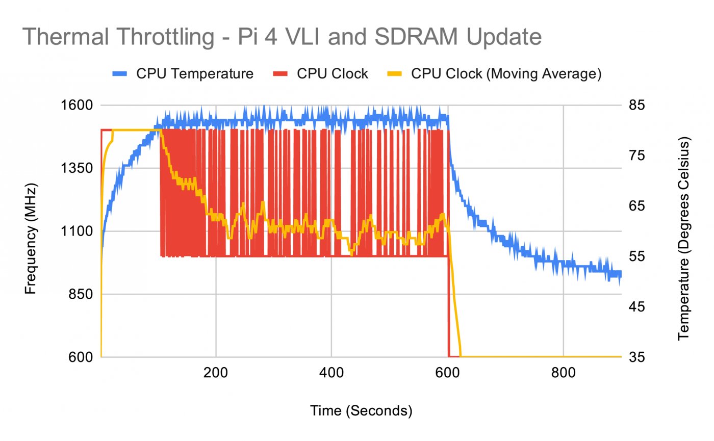
Raspberry Pi’s own documentation — the “Heating and cooling Raspberry Pi 5” article and the frequency-management reference on raspberrypi.com — states the Pi 5’s thermal thresholds plainly: the SoC begins throttling the ARM cores back once the junction temperature reaches 80 °C, and throttles further, pulling back both the ARM cores and the GPU, once it crosses 85 °C. This is a genuinely more aggressive thermal profile than the Pi 4’s, a consequence of the Pi 5’s higher sustained performance ceiling on the same class of passive cooling most builders reach for by default; Raspberry Pi’s own marketing around the Active Cooler acknowledges as much, positioning active cooling as the appropriate solution for sustained load rather than an optional nicety.
What this means concretely inside the PiFlux’s 574 g chassis: independent third-party thermal testing has found a bare, uncooled Pi 5 reaching roughly 86–87 °C under sustained stress-test load — squarely into the hard-throttle band — while the same test with the official Active Cooler fitted stabilised around 59 °C under the same load, comfortably clear of both thresholds. Those figures are for a Pi 5 on an open bench, not inside a closed chassis; a confined internal air volume with limited passive convection — the PiFlux’s actual operating environment — will generally run warmer than an open-bench measurement at the same workload, because a sealed enclosure has less opportunity to shed heat to ambient air without forced airflow. That is the physical reason a device built around continuous or repeated CPU-saturating workloads benefits from active cooling specifically, rather than relying on the Pi 5’s own thermal design margin as an open board would. The practical read for a PiFlux owner: brief bursts of full CPU load are unlikely to be a problem even without active cooling, since thermal mass takes time to heat up and the firmware’s throttling response is itself a safety margin, not a failure mode — but sustained, minutes-long CPU-saturating work inside the closed chassis is the scenario where the gap between “passive is fine” and “passive throttles” actually shows up, and it is the scenario the Active Cooling System addresses (§4.3).
4.4.2 NVMe heat contribution
The NVMe drive shares the same confined air volume and adds its own heat load on top of the Pi 5’s. Modern NVMe controllers in the compact 2230/2242 form factors the PiFlux chassis accommodates (Volume 3) generate meaningful heat under sustained sequential writes — the M.2 specification’s own power budget caps bus power at roughly 7 W, and controller vendors note that even within that ceiling, a small-form-factor drive under sustained load can push its own die temperature toward 80–100 °C in poorly-ventilated conditions, because the same compact form factor that makes 2230/2242 drives fit the PiFlux’s chassis also gives them less surface area to shed heat passively than a full-size 2280 drive would have. Consumer NVMe controllers generally implement their own thermal throttling, commonly triggering somewhere in the 70–80 °C range depending on the specific controller, independent of whatever the Pi 5’s own SoC is doing.
In practice this means the Pi 5 and the NVMe drive are throttling against two separate thermal ceilings that happen to share one enclosure’s air. Under light or intermittent NVMe access the drive’s own heat contribution is small enough to be a non-issue; under sustained heavy write activity happening simultaneously with sustained CPU load — a genuinely demanding combined workload, not the PiFlux’s typical field-use case — both components are working against their own throttle points at once, and the shared confined air volume means neither has as much thermal headroom as it would have on an open bench with its own separate cooling. Whether the M.2 Mod board itself provides any thermal interface material or a heat-spreading path from the NVMe drive to the chassis is not documented in Carbon Computers’ published materials for this add-on, and remains [VERIFY against the physical M.2 Mod hardware or its installation instructions] — a detail Volume 6’s assembly coverage is the more natural place to confirm once the hardware is in hand.
4.4.3 The Active Cooling System
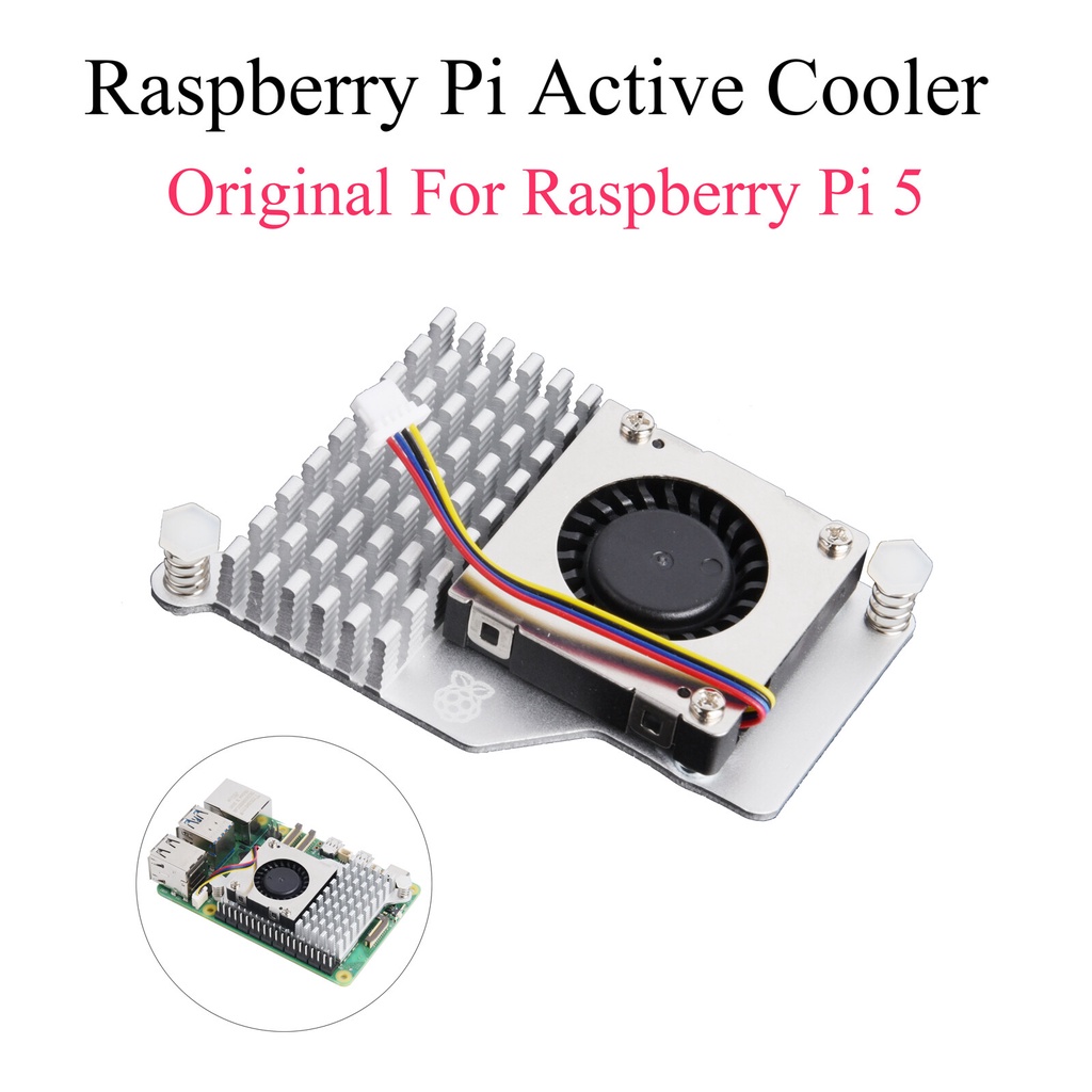
Carbon Computers’ product page is clear on how the Active Cooling System is sold, even though it is thin on the cooler’s own specs. It ships standard on the complete (“Plug & Play”) units — the page lists “Active Cooling Included” as a headline feature — and is not included with the Barebones Kit, which the page explicitly notes ships without cooling. It is not offered as a standalone à-la-carte SKU: the page’s separately-priced add-ons are the Base/Advanced Radio, M.2 Mod, External WiFi Mod, and SD cards — cooling is not among them (Vol 5), which leaves a Barebones builder with no factory path to add the exact cooling the complete units get. What the page does not publish is the cooler’s own specification: its exact fan type, mounting location, noise level under load, and whether it is thermally controlled or fixed-speed all remain [VERIFY against Carbon Computers documentation or the physical unit].
What can be said with reasonable confidence is architectural rather than specific: the Pi 5’s HAT+ connector exposes a standard interface for exactly this class of accessory, and Raspberry Pi’s own official Active Cooler — a $5 aluminium heatsink paired with a temperature-controlled blower fan, delivering up to 1.4 CFM of airflow across the SoC, memory, and power-management IC, powered from the Pi 5’s own 5 V fan header — is the reference design this category of product is built against. Raspberry Pi’s own cooler ramps its fan on at 60 °C, increases speed at 67.5 °C, and runs at full speed at 75 °C, with measured noise in the 35–40 dB range while the fan is actively spinning under load. Figure 4.5’s caption reflects that relationship honestly: the official cooler is “the basis of” the PiFlux’s own Active Cooling System in the sense that it is the architecture any Pi 5 active-cooling accessory in this product category is built around — a blower-and-heatsink assembly mounted over the SoC, driven from the same 5 V fan header, most plausibly with some form of temperature-responsive speed control rather than a fixed-speed fan given how directly the official part’s own thermal-curve approach maps onto the problem. But that is a reasonable inference about the category, not a confirmed statement that Carbon Computers’ own implementation matches the official cooler’s specific fan curve, noise figures, or airflow rating, or that it extends cooling to the NVMe drive as well as the SoC. A builder who wants the PiFlux’s Active Cooling System’s actual specifications — rather than the reference architecture it is plausibly built on — should treat this section as a well-reasoned starting point and confirm the specifics once the part is in hand or fully documented by the manufacturer.
What is more solidly grounded is the reason the Active Cooling System exists at all: §4.1 already showed a bare Pi 5 crossing into hard-throttle territory under sustained stress-test load on an open bench, and the PiFlux’s closed chassis gives that scenario less margin, not more. Active airflow — whatever its specific implementation — addresses exactly the gap between the Pi 5’s thermal design and the sustained-load scenario a portable field computer is more likely to encounter than a desktop workstation is: repeated cycles of heavy compute separated by idle stretches, in an enclosure that cannot rely on passive convection the way an open bench setup can.
4.4.4 Thermal testing methodology
A reader who wants to verify any of the temperature claims in this volume against their own physical PiFlux — rather than trusting third-party bench figures gathered on a different Pi 5 in a different enclosure — can do so with a repeatable procedure using standard Linux tools:
- CPU saturation:
stress-ng --cpu 4 --cpu-method all --timeout 600sloads all four Cortex-A76 cores at maximum for ten minutes, the kind of sustained load §4.1 identifies as the scenario where a closed chassis loses ground relative to an open-bench measurement. - NVMe saturation:
fio --name=writetest --rw=write --bs=128k --size=2G --numjobs=1 --runtime=600 --time_baseddrives sustained sequential writes to the NVMe drive for the same duration, exercising the drive-side heat contribution from §4.2. Running both tools concurrently reproduces the combined-load scenario that stresses both thermal ceilings at once. - Temperature logging:
vcgencmd measure_temppolled at 60-second intervals (a simple shell loop redirecting to a CSV file) gives the SoC’s own temperature over the course of the test; a similar poll of the NVMe drive’s SMART temperature attribute (viasmartctl -a /dev/nvme0, where supported by the drive) gives the corresponding NVMe figure. - Comparison runs: repeating the same procedure with the Active Cooling System active and then passive-only isolates exactly what the active cooling buys in this specific chassis, rather than relying on the official Active Cooler’s open-bench figures (§4.3) as a stand-in for a fitted, closed-chassis result.
This is the methodology by which any of this volume’s temperature claims should be checked before being treated as settled for a specific physical unit — third-party bench figures are a reasonable starting point for planning, not a substitute for a measurement taken in the actual chassis with the actual cooling hardware fitted.
4.5 Governor Configuration for Battery vs. Performance
The Linux kernel’s CPU frequency governor is the practical lever a PiFlux owner has for trading sustained performance against both battery runtime and heat — a lever that is free (no hardware cost) and reversible session to session, unlike the Active Cooling System’s fixed one-time cost. Raspberry Pi OS Bookworm ships with ondemand as the default governor, configured via a udev rule (/usr/lib/udev/rules.d/60-ondemand-governor.rules) rather than a raspi-config script as on older Pi OS releases; the four governors relevant to this discussion are:
performance— locks the CPU at its maximum frequency regardless of load. Maximum responsiveness, maximum power draw, and the fastest route to the thermal thresholds discussed in §4.1. Appropriate for a bench-tethered session where runtime and heat are not concerns.ondemand— the Pi OS default. Scales frequency up aggressively in response to load and back down when idle, using a periodic sampling approach that predates more modern scheduler-aware governors. Reasonable general-purpose behaviour, though some users reportschedutilfeeling more responsive and drawing somewhat less power for equivalent work, since its load estimation ties more directly into the kernel scheduler rather than a fixed sampling interval.schedutil— the modern Linux default outside the Raspberry Pi ecosystem, and available on Pi OS as an alternative toondemand. Tracks demand via the scheduler’s own utilization tracking rather than periodic sampling, and is the governor kernel developers generally recommend overondemandfor contemporary hardware.powersave— caps the CPU at its lowest P-state unconditionally. The most battery-friendly and coolest-running option, at the direct cost of sustained compute throughput; appropriate for a field session — reading documentation, monitoring a slow process, light terminal work — where responsiveness matters less than stretching the runtime figures from §2.4 toward their high end.
Checking and changing the active governor is a matter of reading or writing the per-core sysfs path directly:
cat /sys/devices/system/cpu/cpu0/cpufreq/scaling_governor

# Set powersave across all four cores for the current session
echo powersave | sudo tee /sys/devices/system/cpu/cpu*/cpufreq/scaling_governor

# Or, more conveniently, via cpupower if installed
sudo apt install linux-cpupower
sudo cpupower frequency-set -g powersave
A change made this way reverts on reboot; a builder who wants powersave (or schedutil) to persist should set it via a systemd unit or an entry in /etc/rc.local, following whatever persistence mechanism the specific Pi OS release documents.
The governor choice connects directly back to both this volume’s earlier sections. Lower-frequency operation under powersave reduces the Pi 5’s own draw toward the idle end of the range in §2.1’s table, which pushes the runtime math in §2.4 toward its higher-end estimates — genuinely useful for a session where five-plus hours matters more than peak responsiveness. It also reduces junction temperature directly, since a CPU running at a lower sustained frequency generates less heat per unit time; for light workloads, this can keep the Pi 5 comfortably under the Active Cooling System’s fan-activation threshold entirely (§4.3’s reference design, the official Active Cooler, does not spin its fan until 60 °C), meaning a powersave-governed light-use session may run in near-silence even with the Active Cooling System fitted and powered. The trade-off is symmetric and worth stating plainly: a builder chasing maximum sustained compute throughput should expect performance (or the ondemand/schedutil default under real load) to draw toward the higher end of §2.1’s ranges, run toward the low end of §2.4’s runtime estimates, and rely on the Active Cooling System actually being fitted and working to stay clear of the throttle thresholds in §4.1 during any sustained session.
4.6 Resources
Table 3 — 6. Resources
| Resource | URL |
|---|---|
| Raspberry Pi — “Heating and cooling Raspberry Pi 5” | https://www.raspberrypi.com/news/heating-and-cooling-raspberry-pi-5/ |
| Raspberry Pi frequency-management documentation | https://www.raspberrypi.com/documentation/computers/raspberry-pi.html |
| Official Raspberry Pi Active Cooler product page | https://www.raspberrypi.com/products/active-cooler/ |
| Official Active Cooler product brief (PDF) | https://datasheets.raspberrypi.com/cooling/raspberry-pi-active-cooler-product-brief.pdf |
| raspberry.tips — Raspberry Pi power consumption 2026 (all models compared) | https://raspberry.tips/en/raspberrypi-tutorials/raspberry-pi-power-consumption-update-2026-all-models-compared |
| Jeff Geerling — Raspberry Pi 5 power-consumption coverage | https://www.jeffgeerling.com/blog/2023/reducing-raspberry-pi-5s-power-consumption-140x/ |
Pi 5 vcgencmd reference | https://www.raspberrypi.com/documentation/computers/os.html |
| Active Cooling System (Carbon Computers) | https://carboncomputers.us/products/pi-flux |
| Vol 2 — Choosing the Pi 5 (RAM and PCIe) | ../../PiFlux/02-inputs/volume_sources/vol2.md |
| Vol 3 — M.2 Storage | ../../PiFlux/02-inputs/volume_sources/vol3.md |
| Vol 6 — Full Build with All Add-Ons (Active Cooling System assembly) | ../../PiFlux/02-inputs/volume_sources/vol6.md |
| DFCD Vol 5 — Power System (cross-references this volume) | ../../DFCD/02-inputs/volume_sources/vol5.md |
Comments (0)