DFCD · Volume 5
Power System
NP-F battery, 7.2 V to 5.1 V step-down conversion, runtime math, and charging
5.1 The NP-F Battery Format
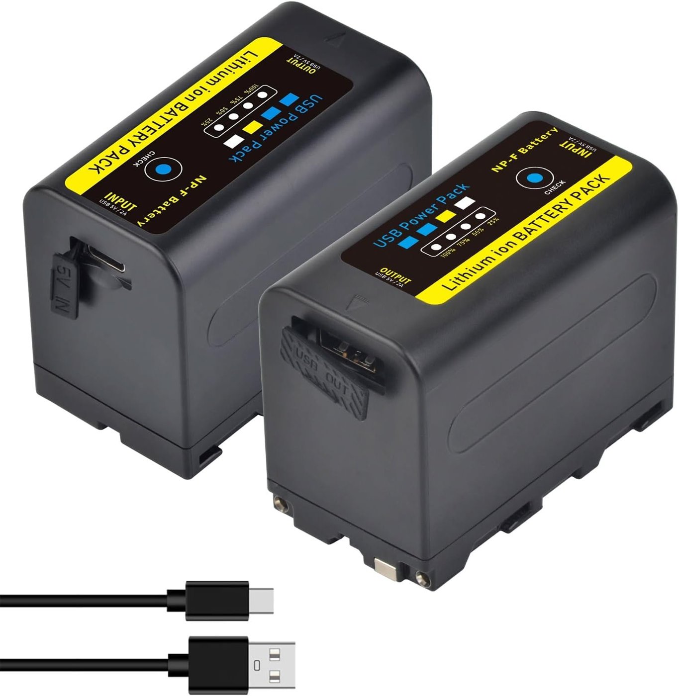
The NP-F format originates in Sony’s camcorder battery line and has, over roughly three decades, become a de facto standard well beyond Sony’s own products. The “L-series” shell — sold across three common sizes, NP-F550, NP-F770, and NP-F970, smallest to largest — presents a flat plastic body with a pair of spring-loaded contact blades that slide onto a matching bracket, plus (on genuine Sony packs) a small data contact used to report charge level to the host camera. Nominal output is 7.2 V, consistent with a 2-cell lithium-ion pack (roughly 8.4 V at full charge, sagging toward 6.0 V near the BMS cutoff under load) — a discharge curve shape any 2S lithium-ion pack shares, not something specific to NP-F. What NP-F contributes is not a novel cell chemistry but a mechanical and electrical standard: any manufacturer building to the L-series footprint produces a battery that drops into any bracket built to the same standard, and after decades of use in professional video production, camera monitors, LED lights, and now cyberdecks, that footprint is supported by an enormous range of third-party packs, chargers, and mounting brackets.
That ecosystem depth is the practical reason the DFCD adopted the format over the alternatives a scratch-built power system might otherwise reach for. A bare LiPo pouch cell is the lightest, most energy-dense option per gram, but it arrives as a bare cell: the builder must add protection circuitry, a charge controller, a connector, and — critically in a workshop environment — some way to prevent a puncture or crush event on an unprotected pouch sitting inside a 3D-printed chassis that will be picked up, set down, and occasionally dropped. Loose 18650 cells solve the puncture-risk problem with a metal can, but still need a holder, a protection PCB, and a charge management circuit the builder is responsible for getting right. A generic USB power bank sidesteps all of that — it is already a complete, protected, chargeable battery — but power banks are built as a sealed appliance with a fixed USB output, not as a battery designed to slot into a purpose-built bay with a clean two-wire tap to a step-down module, and few power banks are shaped to fit a slim rectangular bay the way an NP-F pack is. The NP-F format sits at the useful middle: a complete, protected, mechanically standardised battery pack, available in a range of capacities in the same footprint, that a chassis designer can build a bay around with confidence that the part will remain sourceable for years.
The video-production heritage also explains a specific field habit worth noting even though it isn’t confirmed for the DFCD: professional camera operators using NP-F packs commonly keep several charged spares and hot-swap a depleted pack for a fresh one between shots, because many camera bodies and monitors built around the format include a small holdup capacitor that bridges the brief gap during a pack swap without the device losing power. Whether the DFCD’s power module includes anything analogous — and so whether a builder could genuinely swap NP-F packs without powering down the Pi 5 mid-session — is not documented in the upstream hardware list or wiki pages reachable for this volume, and this volume will not assume it. A builder wanting that capability should treat it as an open question for Volume 4’s wiring documentation rather than a given.
The specific pack the reference build uses adds one more convenience on top of the format’s own advantages: a built-in USB-C charging input, covered next.
5.2 The Reference Battery: 10050 mAh NP-F Pack
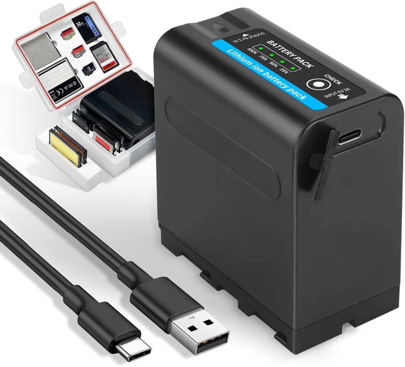
The reference build’s battery, confirmed against the Scandinavian Photo (Norway) listing linked from the upstream hardware list (Volume 2, §5.1), is a Jupio NP-F970, 10,050 mAh, with a built-in USB-C charging input. Jupio is a third-party battery manufacturer, not Sony; the pack is built in the largest of the three common NP-F shells (F970) but carries meaningfully more capacity than a stock Sony NP-F970 (commonly cited in the 6,000–6,600 mAh range, with some variation across sources) — a common practice among third-party NP-F packs aimed at video lights and field monitors, where builders compete on capacity within a fixed, standardised shell rather than on shell size. Nominal voltage is 7.2 V, the standard figure for a 2-cell pack in this format.
The energy math starts from the nameplate figures and is straightforward:
Nominal energy (Wh) = Capacity (Ah) × Nominal voltage (V)
10.05 Ah × 7.2 V = 72.36 Wh, which this series rounds to ≈72.4 Wh. That figure is the pack’s rated energy content — the number on the label, not the number actually available to run the Pi 5. Two losses stand between nameplate capacity and usable output. First, a lithium-ion pack’s built-in protection circuit cuts the pack off before the cells reach true 0% charge (to protect cell longevity), and the cell voltage sags under load in a way that means the last few percent of nominal capacity is delivered at a voltage the load can’t use efficiently — real-world usable energy for a healthy consumer lithium-ion pack is typically 85–90% of nameplate, not the full figure. Second, whatever the pack delivers at its own terminals still has to pass through the step-down module before it reaches the Pi 5, which is its own loss covered in §3 and folded into the runtime math in §4.
Applying just the first factor: 72.4 Wh × 0.85–0.90 ≈ 62–65 Wh usable at the battery’s own output contacts before the step-down module’s own conversion loss is applied. This series carries that range forward rather than picking a single number, because neither this pack’s exact protection-circuit cutoff voltage nor its real-world capacity fade with age is published — treating either as a fixed constant would manufacture false precision the underlying part doesn’t support.
One capacity-inflation caution is worth stating plainly, because it’s a known issue with third-party NP-F packs generally: some vendors in this market print optimistic mAh figures that don’t survive an independent capacity test. Nothing in the sourcing trail for this specific Jupio unit suggests that problem here — Jupio is an established battery brand carried by a mainstream photography retailer rather than an anonymous marketplace listing — but a builder who wants certainty rather than reasonable confidence should run an independent discharge test against the 10,050 mAh figure before relying on the runtime numbers in §4 for anything safety-critical.
Physically, the pack’s standard NP-F contact blades mate to the step-down module’s input leads inside the DFCD’s power module, the same mechanical interface used across the NP-F ecosystem — part of why this format was a sound choice for a printed chassis bay (§1): the mounting bracket geometry is well understood and widely documented, not something the DFCD’s designer had to invent.
5.3 Joy-it Step-Down Conversion (7.2 V → 5.1 V)
5.3.1 Module Specification
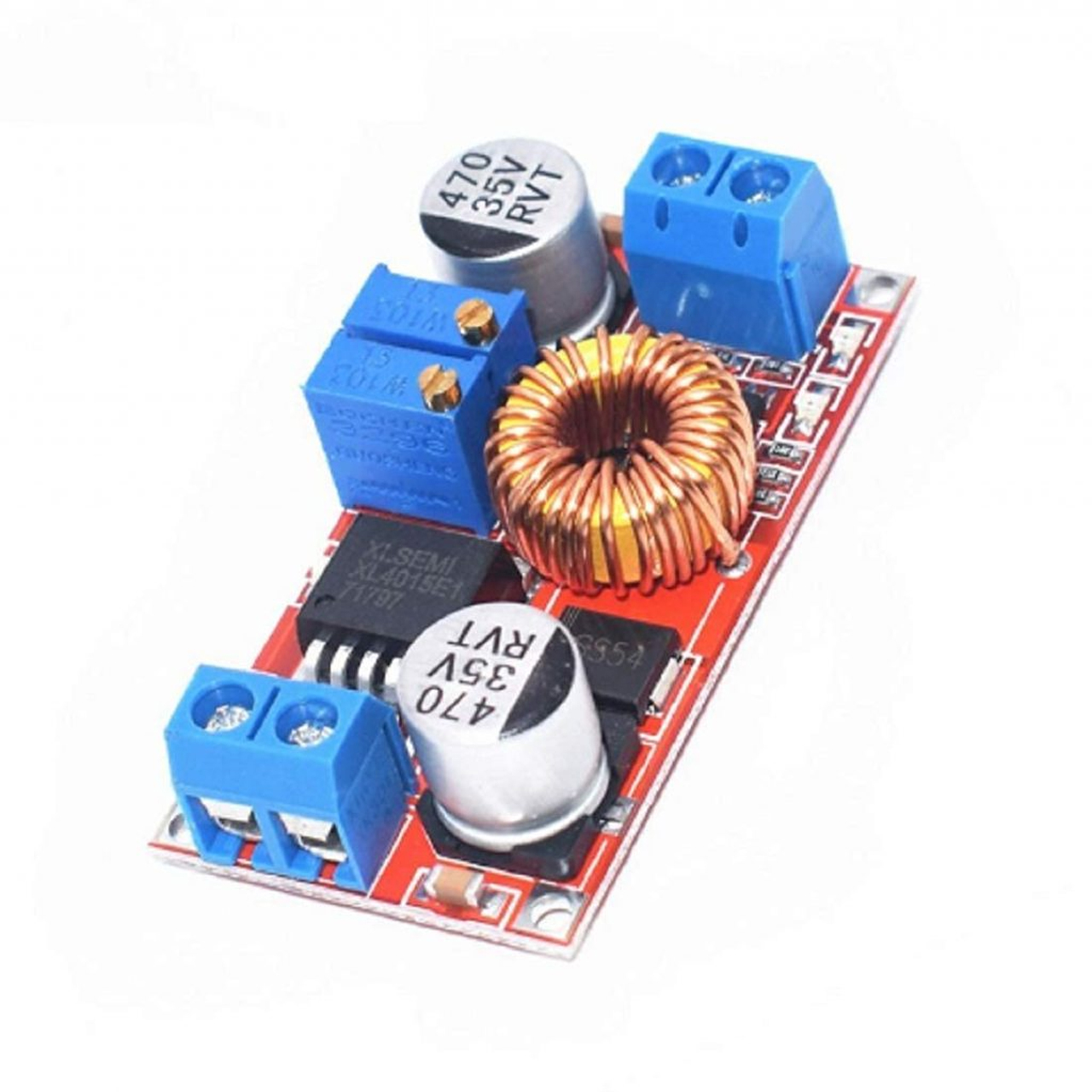
The step-down module is the Joy-IT PiEnergy Mini (RB-PE01), confirmed against the Kjell & Co listing linked upstream (local part 88409) in Volume 2, §5.2. It is a buck (step-down) converter: 6–36 V DC input, regulated 5.1 V output at up to 3 A, built around an STM8S001J3 microcontroller that handles an on/off pushbutton and a GPIO4 signal line to the host, with a pre-mounted heatsink and a 2-pin 2.54 mm fan header. The board itself is tiny — 23 × 56 × 11 mm at 15 g — small enough to sit inline in the power module without meaningfully affecting the chassis’s internal layout.
Buck conversion works by switching the input voltage on and off at high frequency through an inductor and smoothing capacitor, regulating the output by adjusting the switch’s duty cycle rather than by dropping the excess voltage as heat the way a simple linear regulator would. That switching approach is why a buck converter can be efficient even across a meaningful voltage drop: a well-designed buck converter running from roughly 6–8 V down to 5.1 V — a modest step-down ratio, not an extreme one — typically achieves 85–92% conversion efficiency at a moderate fraction of its rated current, with efficiency typically softening somewhat at the very light and very heavy ends of its load range. Joy-IT’s listing for the PiEnergy Mini does not publish a measured efficiency curve, so this volume works from the general figure for a buck converter of this class and voltage ratio rather than a datasheet number specific to this board — a genuine but reasonably tight uncertainty band, carried into the runtime math in §4.
5.3.2 Pi 5 Power Requirements
The Raspberry Pi 5’s official power specification, confirmed against Raspberry Pi’s own documentation, gives two supported profiles: 5 V at 5 A (25 W) via USB-C Power Delivery for full performance, or a fallback 5 V at 3 A (15 W) profile that caps the total power available to the Pi 5’s own USB-A ports at a nominal 600 mA (rising to roughly 1.6 A once a genuine 5 A PD negotiation is detected). The 5 A/25 W figure is what Raspberry Pi’s own 27 W official power supply is built to deliver, and it’s the profile the Pi 5 requests first; the board falls back automatically if a connected supply can’t or won’t offer it.
This is where the DFCD’s power path runs into a real, worth-stating-plainly design constraint. The PiEnergy Mini is a fixed-output regulator, not a USB Power Delivery source — nothing in its published specification describes a PD controller negotiating a power contract over the USB-C CC lines, and its own output ceiling (3 A at 5.1 V, 15.3 W) sits almost exactly at the Pi 5’s documented 3 A/15 W fallback tier rather than its 5 A/25 W top tier. The most plausible reading, absent a datasheet that spells out the module’s CC-line behaviour, is that the DFCD’s Pi 5 runs on the Pi’s own 3 A fallback profile rather than the full 5 A profile — which in turn means the Pi 5’s own USB-A ports (feeding the keyboard and trackball, per Volume 4’s wiring) see the tighter 600 mA collective budget rather than the roughly 1.6 A available under a genuine 5 A negotiation. That reading is [VERIFY against the actual wiring in Volume 4 — specifically whether the PiEnergy Mini’s output is wired to the Pi 5’s USB-C port at all, or direct to the GPIO 5 V rail, which sidesteps PD negotiation and USB-port budgeting differently again]; this volume states it as the sensible engineering inference from the two modules’ published specs, not as a confirmed fact.
In practical terms this matters less than the numbers might first suggest, because the Pi 5 essentially never draws its full 25 W ceiling in a FreeCAD-at-the-bench workload — that ceiling exists for the worst case of a fully PD-negotiated supply feeding power-hungry USB peripherals (spinning hard drives, for instance) simultaneously with a saturated CPU. Section 4’s power budget below shows the DFCD’s realistic total system draw sitting comfortably under the PiEnergy Mini’s 15.3 W ceiling for the workload this device is designed around. The genuine risk case is a worst-case pile-up — CPU and GPU both near saturation while the display sits at full brightness and a USB peripheral draws its own peak current simultaneously — where the module’s fixed 3 A ceiling could be approached. The practical symptom of exceeding it would be an under-voltage condition (the Pi 5’s firmware flags this visibly, and the CPU may throttle in response) rather than damage to either module, but it is a real headroom question a builder should keep in mind when adding USB peripherals to the rear rails rather than something to dismiss because the two numbers happen to work out closely.
For the Pi 5’s own power draw across workload types — idle, light desktop use, CPU-saturating compute, GPU-bound rendering — this volume does not re-derive figures the sibling PiFlux deep-dive already covers in depth; see §6 below.
5.3.3 Wiring and Protection
Sizing the wire between the battery, the step-down module, and the Pi 5 comes down to the same current figures used above. At the module’s rated 3 A output, the wiring downstream of the converter needs to be sized for that continuous current; upstream, at 7.2 V input and accounting for the converter’s own 85–92% efficiency, the input-side current for a full 15.3 W output load works out to roughly 2.3–2.5 A. Both figures sit in the same rough band, and for short chassis-internal runs a common rule of thumb — 20 AWG stranded copper comfortably carries 3 A continuous with negligible voltage drop and temperature rise over runs of a few tens of centimetres — gives adequate margin; 18 AWG is a reasonable step up where a builder wants extra headroom or where run length grows. The upstream hardware list and reachable wiki pages do not publish the exact gauge used in the reference build, so the specific wire spec remains [VERIFY against Volume 4’s wiring documentation or the physical build]; the guidance above is general good practice for the current levels involved, not a confirmed as-built spec.
On protection: neither the PiEnergy Mini’s listing nor the upstream hardware list documents a separate inline fuse between the battery and the step-down module. The STM8S001J3 microcontroller onboard the PiEnergy Mini plausibly implements some level of over-current or under-voltage protection in firmware — this is common practice for microcontroller-supervised buck modules of this class — but that is an inference from the part’s general design category, not a confirmed datasheet feature, and this volume will not claim a specific protection threshold the manufacturer hasn’t published. A builder wanting a hard guarantee against a wiring fault or a shorted downstream connector should consider adding a small inline fuse (a 3–4 A fast-blow fuse or resettable polyfuse rated appropriately) at the battery’s output regardless of what the step-down module may or may not already provide — cheap insurance against a chassis-internal short that a microcontroller’s software-based protection might not catch as fast as dedicated fusing would.
5.4 Runtime Math
5.4.1 System Power Budget
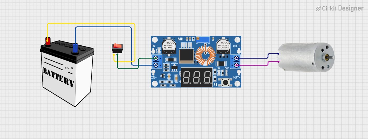
The total system draw on the 5.1 V rail is the sum of the Pi 5’s own load, the 10.1-inch IPS display, the NOS 450 TKL keyboard, the trackball, and the PiEnergy Mini’s own housekeeping current. Building this budget from verifiable figures rather than from a single invented total is the point of this section.
For the Pi 5 itself, this volume adopts the workload-tier framing the sibling PiFlux power volume uses (see §6): third-party power measurements for the Pi 5 (raspberry.tips’ 2026 benchmark set, cross-checked against Jeff Geerling’s independent measurements) place headless idle draw around 2.7–3.6 W, moderate desktop/video-playback load around 5.7–6.8 W, and CPU-saturating four-core load around 8.8 W, with combined CPU + NVMe + 4K-display scenarios reported as high as ~16 W in stress testing that doesn’t reflect this build (the DFCD has no NVMe expansion). None of these figures come from Raspberry Pi’s own published documentation, which — confirmed by direct check of raspberrypi.com — states the supported power delivery profiles but does not publish idle/load power-draw numbers itself; the figures above are reputable third-party measurements, not a manufacturer spec, and are presented on that basis. FreeCAD viewport navigation and light editing on a moderate-complexity assembly sits between the idle and CPU-saturating extremes — sustained enough to keep the CPU above idle but rarely pegging all four cores continuously the way a compile or stress test would — so this volume assumes a FreeCAD mid-load draw of roughly 4–6 W, using 5 W as the central planning figure.
For the display, Volume 2 (§2.1) could not confirm the exact panel behind the upstream AliExpress listing, but the 10.1-inch IPS-touch-HDMI category it belongs to is well characterised by comparable Waveshare products in the same class: manufacturer figures for Waveshare’s 10.1-inch HDMI LCD line show roughly 2.75–3.75 W with the backlight on, dropping sharply when the backlight is dimmed or disabled. This volume uses that category-typical range, not a confirmed spec for the exact panel, consistent with Volume 2’s own hedge on this component.
Table 1 — 4.1 System Power Budget
| Component | Typical draw (W) | Notes |
|---|---|---|
| Raspberry Pi 5 (FreeCAD mid-load) | ~4–6 W (central estimate 5 W) | Third-party benchmarks, not a Pi 5 manufacturer figure; see §6 |
| 10.1-inch IPS display | ~2.75–3.75 W (backlight on) | Category-typical for this panel class; exact model unconfirmed (Vol 2 §2.1) |
| NOS 450 TKL keyboard | ~0.3 W | USB HID; RGB backlighting could add draw if left enabled |
| Trackball (Marble harvest) | ~0.05 W | USB HID, optical sensor — low and largely fixed |
| Joy-it module housekeeping | ~0.1–0.2 W | No published quiescent-current figure; estimated for a microcontroller-supervised buck module of this class |
| Total (estimated) | ≈7.2–10.3 W; central estimate ≈8.75 W | Sum of the ranges above; see §4.2 for the runtime this implies |
5.4.2 Estimated Runtime
Runtime (hours) ≈ Delivered energy (Wh) / System power (W)
Working the figures through in order:
- Nominal battery energy: 7.2 V × 10.05 Ah = 72.4 Wh (§2).
- Usable energy at the battery’s own terminals: applying an 85–90% real-world derating for BMS cutoff behaviour and load-sag losses (§2) gives 72.4 × 0.85 to 72.4 × 0.90 ≈ 62–65 Wh.
- Energy delivered to the 5.1 V rail after step-down conversion: applying the PiEnergy Mini’s estimated 85–92% conversion efficiency (§3.1) to that usable-energy range gives 62 × 0.85 to 65 × 0.92 ≈ 53–60 Wh delivered to the load side of the converter. This volume carries the slightly tighter ≈53–58 Wh as its working figure, keeping the efficiency assumption toward the middle of the stated band rather than its most optimistic edge.
- System power draw: ≈7.2–10.3 W, central estimate 8.75 W (§4.1).
- Runtime: dividing the delivered-energy range by the system-power range gives a low-end estimate of 53 Wh ÷ 10.3 W ≈ 5.1 hours and a high-end estimate of 58 Wh ÷ 7.2 W ≈ 8.1 hours, with the two central estimates (55.5 Wh ÷ 8.75 W) landing at ≈6.3 hours.
The honest answer, then, is a realistic runtime band of roughly 5 to 8 hours for a typical FreeCAD workshop session with the display active at a comfortable brightness, centred around 6–7 hours — not a single decimal-precision figure, because neither the battery’s real-world usable capacity, the converter’s exact efficiency, nor the Pi 5’s draw under this specific workload has a published, test-verified number this series can point to. A builder who wants a tighter figure than this range can get one cheaply: a USB-C power meter inline between the PiEnergy Mini and the Pi 5, logged over a real FreeCAD session, would resolve steps 3–5 to measured rather than estimated numbers in an afternoon.
Two levers shorten or extend that range in practice. Dimming the display meaningfully — display backlight is one of the largest single line items in the budget after the Pi 5 itself — buys real runtime; so does keeping the CPU governor at a lower power state during reference-only sessions where viewport smoothness matters less than battery life (a lever explored in the sibling PiFlux power volume, §6 below, in the context of the Pi 5’s own governor options).
5.5 Charging
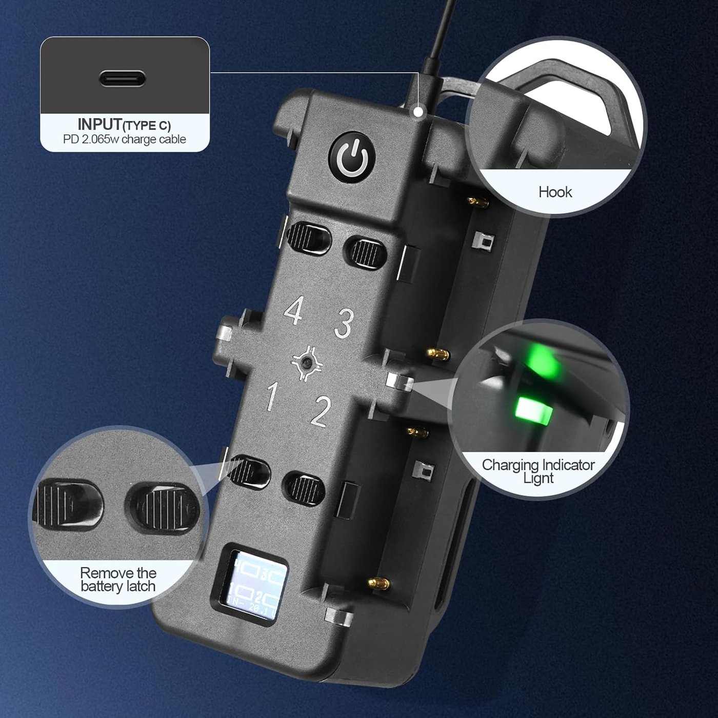
The Jupio NP-F970 recharges through its own built-in USB-C input — the feature that makes this pack meaningfully more convenient than a traditional NP-F pack, which typically requires a dedicated cradle-style charger rather than accepting a common USB-C cable directly. The specific charge voltage and current the pack’s internal charge controller accepts is not published in the Scandinavian Photo listing retrieved for this series (Volume 2, §5.1 flags the same gap), so the pack’s actual charge rate remains [VERIFY against the unit’s own markings, its included documentation, or a clamp-meter measurement once the hardware is in hand].
What can be said without inventing a spec: USB-C-charging battery packs in this capacity class commonly implement charge inputs somewhere in the 5 V/2 A (10 W) to 9 V/2 A (18 W, via basic USB-PD or a proprietary fast-charge profile) range. Applying that plausible range to the pack’s 72.4 Wh nominal capacity and a typical ~80% charging efficiency (lithium-ion charging isn’t lossless either, particularly toward the top of the charge curve where current tapers) gives a full recharge-from-empty time of roughly 72.4 ÷ (0.8 × 10) ≈ 9 hours at the slower end of that plausible range, down to 72.4 ÷ (0.8 × 18) ≈ 5 hours at the faster end. That is a wide band precisely because the pack’s actual charge-controller spec isn’t published — a builder should treat it as bracketing the likely reality rather than as a confirmed number, and a workshop use pattern of topping the pack up during a lunch break or an overnight sit is realistic across the whole range regardless of exactly where the true figure falls.
Whether the DFCD can run while the battery charges — genuine pass-through, UPS-style operation — depends entirely on the pack’s internal charge/discharge switching design, and this is not documented in any source reachable for this volume. Some USB-C-charging battery packs support simultaneous charge-in and discharge-out; others disconnect the output during a charge cycle, or only support pass-through up to a lower current limit than full discharge current. This is a per-model BMS design choice that generic retailer listings essentially never document, and it directly affects whether a builder can leave the DFCD running on external power indefinitely (charger permanently attached) or must plan around a genuine charge/discharge cycle. This remains [VERIFY against the physical unit once acquired, or against any documentation Jupio publishes for the NP-F970 line] — a detail worth testing early in the build rather than assuming either way.
5.6 Cross-Reference: PiFlux Power and Thermal Volume
The Raspberry Pi 5’s power draw and thermal behaviour under sustained load — the workload-by-workload figures this volume draws on in §4.1, and the deeper thermal-throttling and CPU-governor material referenced in §4.2 — are the subject of the sibling PiFlux deep-dive’s Volume 4, “Power & Thermal with M.2” (../../PiFlux/02-inputs/volume_sources/vol4.md). That volume is where the Cyberdecks hub’s Pi 5 platform-depth material on this topic lives, per the division of labour both series establish in their own Volume 1s: the PiFlux series owns Pi 5 platform characterisation across the hub, and the DFCD series cross-references it rather than re-deriving the same figures independently.
Specifically, the PiFlux power volume covers:
- The Pi 5’s power envelope across workload tiers (idle, light desktop use, sustained CPU-bound compute, GPU-bound rendering) in more granular detail than the mid-load estimate this volume adopts for the FreeCAD use case
- Thermal characterisation under sustained load, including the Pi 5’s documented soft- and hard-throttle temperature thresholds and the margin a given cooling solution provides against them
- CPU frequency governor options (
performance,powersave,schedutil,ondemand) and their measured effect on both power draw and heat — directly relevant to the runtime-versus-responsiveness tradeoff noted at the end of §4.2 above - The Pi 5’s behaviour when NVMe storage shares the power and thermal budget — not directly applicable to the DFCD, which has no M.2 expansion, but useful context for a reader comparing the two decks’ compute platforms
A builder who wants the Pi 5’s power and thermal story at full platform depth — independent of either deck’s chassis — should start there rather than treating this volume’s §4 as the complete word on Pi 5 power behaviour. This volume’s job is narrower and more specific: taking the Pi 5’s general power profile as a given and working out what it means for one particular battery, one particular step-down module, and one particular runtime expectation in a 3D-printed workshop deck.
Comments (0)