DFCD · Volume 4
Assembly & Wiring
Screen slider mechanism, trackball module, power path, rear USB rails, shoulder mounts, and cable management
4.1 Assembly Sequence Overview
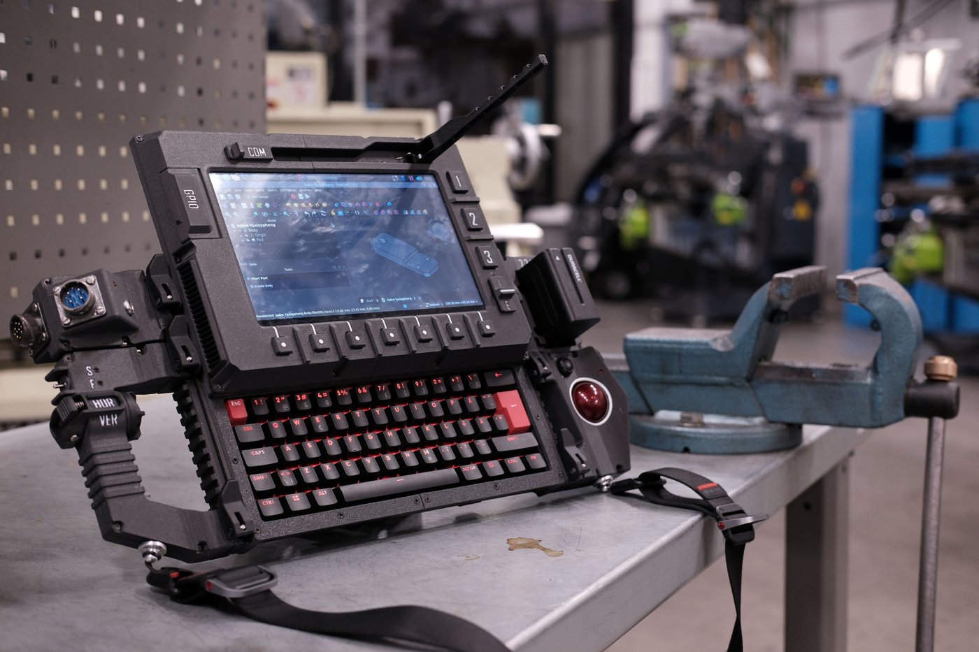
The DFCD’s sliding screen and rear drag-chain constrain the build order more than a static enclosure would: cables have to cross a moving joint, the chain has to be attached before the chassis can close around it, and the screen sub-assembly is easiest to wire on the bench before it is ever mated to the guide rods. Two of the upstream project’s four wiki build-guide pages were reachable for this volume — the chassis guide and the screen-unit guide — and both describe an assembly-by-subassembly approach rather than a single linear sequence; the wiki has no separate trackball-module or left-connection-module guide, so their internal steps are undocumented in the wiki. The sequence below synthesizes what those two reachable pages describe, in the order that makes mechanical sense given the drag-chain and rail dependencies; it is not a verbatim transcription of a numbered upstream step list, and builders should treat it as a planning aid rather than a substitute for the wiki pages once they are reachable.
- Print and post-process every chassis, module, and drag-chain part (Volume 3).
- Assemble the lower chassis: join the two printed chassis halves — the upstream guide describes this as being “welded” with a soldering iron, melting filament into the seam rather than fastening it mechanically, which makes this step irreversible — install the ventilation frames and rail mounting points, and wire the rear rail sockets for power and USB signal (§5).
- Mount the Joy-it step-down module and wire it to the NP-F battery bay contacts; verify the module’s output voltage before wiring anything downstream of it (§4).
- Build the screen unit as a separate subassembly off the chassis: weld its base, mount the rod clamps to the base’s backside, install the screen-frame-mounted tactile buttons and slide switch, clamp in the LCD, and screw the cable chain down to the frame once the screen-side cables are connected (§2, §8).
- Build the trackball module as its own subassembly: harvest and mount the Logitech Marble electronics (§3).
- Mate the screen unit to the chassis via the guide rods and linear bearings, engaging the spring-loaded release latch (§2.1).
- Route the drag-chain cable bundle from the screen unit into the stationary chassis and connect it to the Pi 5 side (§8).
- Mount the Raspberry Pi 5 (on its Joy-it cooler) and the keyboard, and wire their USB connections (§2.3).
- Assemble and mate the 0B, 2B, Y2M, and pogo-pin connectors that join modules to the chassis (§9).
- Attach the trackball module and, once wired, the left connection module to the rear rails via the NATO/picatinny rail clamps, and fit the strap (§5, §7).
- Run the final pre-power-on checks (§10).
A YouTube thumbnail matching the finished device (visually consistent with the workbench photographs used throughout this volume) exists at the build video’s URL (https://youtu.be/gIWp_F9PPzI), but its description text and any chapter markers could not be retrieved for this volume — automated fetch returned only the page’s footer navigation. Builders following along on video should expect the on-screen sequence to fill in gaps this section cannot: notably the exact order of operations within the trackball harvest and the left connection module wiring, both of which remain [VERIFY against the video directly].
4.2 Screen and Keyboard Slider Mechanism
4.2.1 Rail Assembly
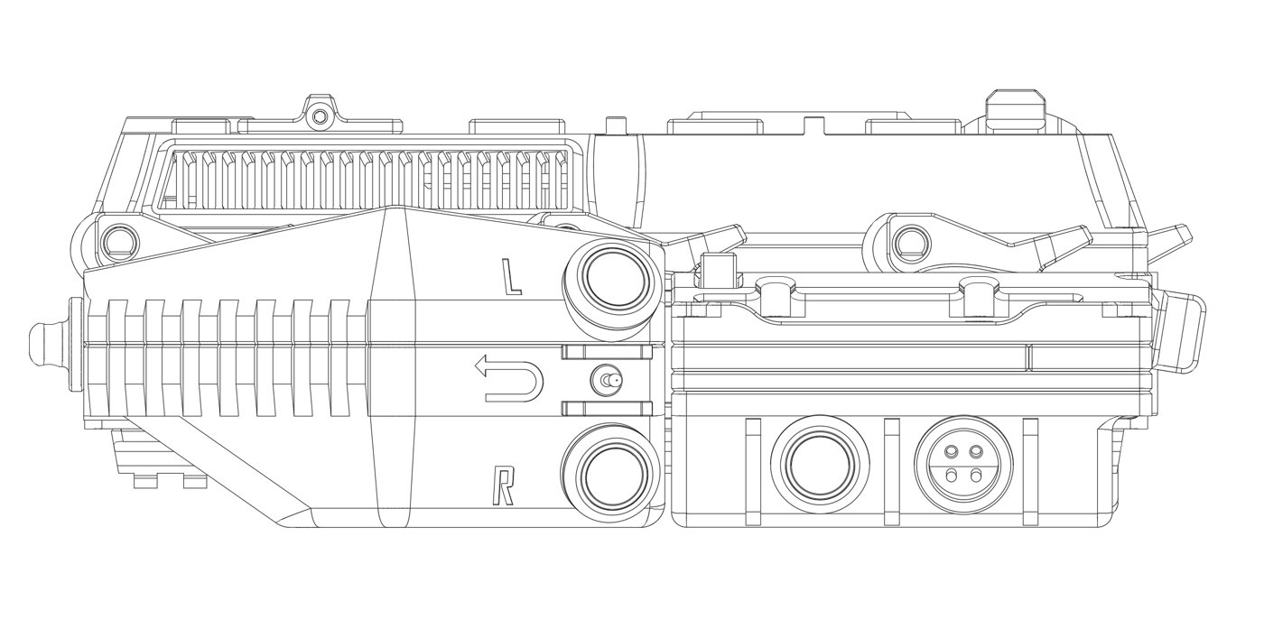
The chassis build guide describes linear bearings being inserted into printed bearing holders, which are then placed into the upper chassis sections — the mechanical basis for the screen’s sliding travel. The screen’s own base plate is welded (soldering-iron plastic weld, the same technique used to join the lower chassis halves) and then fitted with rod clamps mounted to its backside using screws and a nut. The guide rods are then installed through the upper chassis bearings and into those clamps, which the guide describes as “locking the base down” and establishing the travel path.
Given the device’s stated form factor — a screen that sits above a hidden keyboard and must retract to reveal it (Volume 1) — and the use of parallel guide rods with linear bearings rather than a hinge or a single pivot, the mechanism is a vertical slider: the screen rides straight up off the keyboard well rather than swinging or sliding sideways. This reading is consistent with everything the reachable wiki pages describe, but the exact travel distance, the hard stops at each end of travel, and any friction adjustment (a shim, a felt strip, or simple bearing preload) are not given in the retrieved content and remain [VERIFY against the build video or a physical unit].
The chassis guide also documents a dedicated screen-release mechanism: a spring-loaded latch built from a cut screw or threaded rod used as a pin, paired with a spring salvaged from a ballpoint pen. This is a manual detent, similar in function to a laptop lid-release button — it holds the screen down in the closed position and gives a small spring-assisted kick when released, after which the screen is slid up by hand along the guide rods. No upstream figure for spring rate, pin diameter, or the exact detent geometry was available; a builder reproducing this detail should expect to size the pin and spring by fit rather than to a published spec.
4.2.2 Display Mounting
Once the sliding base and guide rods are assembled, the screen frame receives the 10.1-inch IPS touch LCD, which the screen-unit guide describes as being inserted and then clamped to the frame — a mechanical retention scheme rather than an adhesive one, consistent with a design meant to be serviced. The display’s video path is the 90-degree micro-HDMI-to-ribbon assembly detailed in Volume 2 §2.2; that ribbon, plus the touch digitiser’s separate USB cable (Volume 2 §2.1), both originate at the moving screen frame and must cross into the stationary chassis. Per the screen-unit guide, this crossing happens through the drag chain, which is screwed down to the screen frame after the LCD and the frame-mounted controls (§2.3 below, §6) are wired — Section 8 covers the chain itself and what else shares it.
4.2.3 Keyboard Installation
The keyboard sits in the stationary lower deck rather than on the moving screen assembly, and per the chassis guide is mounted using its own supplied screws — no separate hardware is called out for it in the retrieved content. Electrically it connects to the Pi 5 as a standard wired USB HID keyboard with no special driver, the same conclusion Volume 2 §3.1 and Volume 6 §4.2 reach from the software side.
The board itself is the NOS C-450 Mini Pro — the upstream hardware list’s “NOS 450 TKL” line item, which Volume 1 and Volume 2 §3.1 already establish is actually a 60%-class 62-key board rather than a true tenkeyless layout. That naming tension matters directly at this assembly step: the keyboard well and the clearance between the keyboard’s top surface and the underside of the closed sliding screen are both cut to one specific footprint in the printed chassis (Volume 3), and a 60%-class board sits in a narrower well than a true TKL board would need. A builder should physically dry-fit the keyboard in the printed well and confirm the screen slides fully closed over it before final assembly, rather than trusting the footprint by name alone.
4.3 Trackball Module

4.3.1 Harvested Electronics Installation
The wiki carries no dedicated trackball-module build-guide page, so the exact harvest and mounting procedure is not independently confirmed here; Volume 2 §4.1 already carries the same caveat and works through the plausible harvest method (desoldering the ball-cage sensor assembly intact from a donor Logitech Marble and re-mounting it behind a new ball cutout) as an informed inference rather than a documented fact.
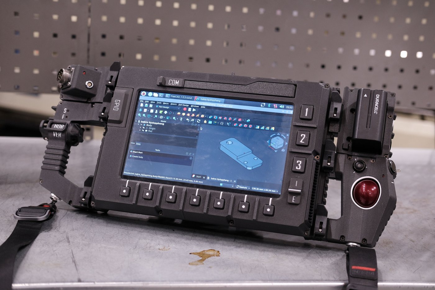
What can be added from direct observation of the finished build is that the assembled photographs (Figures 4.1 and 4.6, and Figure 1.2 in Volume 1) consistently show a red trackball ball seated in a chrome-ringed circular housing on the right-hand module — visually consistent with the red-ball Marble unit pictured in Figure 4.3, and consistent with the harvest claim even without a documented procedure. The module’s USB cable most plausibly reaches the Pi 5 through the right-side rail sockets (EXT2 or EXT3 in the labeling visible in Figure 4.5), since the trackball module sits immediately adjacent to those ports in the assembled unit — a placement inference from the photographs, not a confirmed wiring path, and marked [VERIFY] accordingly.
4.3.2 Trackball Calibration
Once wired, the harvested sensor presents to Raspberry Pi OS as an ordinary USB HID pointing device requiring no special driver. Pointer sensitivity, acceleration, and any scroll emulation the harvested Marble hardware doesn’t natively provide are OS-level libinput settings rather than anything to configure during assembly; Volume 6 §4.1 is the reference for that configuration once the trackball is wired and the OS is installed.
4.4 Power Path
4.4.1 NP-F Battery Integration
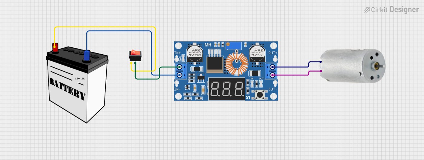
The NP-F pack sits in its own detachable Battery module on the right side of the deck, docked to the central unit by the picatinny rail clamps like the trackball module (Volume 3 §2.1) — not in a bay inside the main chassis body. Its 7.2 V reaches the central unit over the rear rail connectors, where the step-down module converts it to 5.1 V (Volume 5 works through where the converter physically sits). NP-F packs mate through the format’s standard slide-on blade contacts (Volume 2 §5.1), a physically keyed interface — the positive and negative blades differ in position and length, which mechanically discourages inserting the pack backward. That keying reduces but does not eliminate wiring risk: the leads soldered from the module’s contact plate to the step-down input are a separate joint from the pack’s own keyed blades, and a miswired contact plate would defeat the pack’s own polarity protection. Polarity should therefore be verified with a multimeter at the contact plate before the pack is ever inserted, not assumed from the blade keying alone. The retention hardware that holds the pack in its module during transport — a printed latch, a spring clip, or a friction fit — is not specified in the material retrieved for this volume and remains [VERIFY against the upstream STEP files or the assembled unit].
4.4.2 Joy-it Step-Down Module Mounting
The Joy-IT PiEnergy Mini (RB-PE01) — a 23 × 56 × 11 mm board with a fixed 5.1 V output, an onboard on/off pushbutton, and a 2-pin fan header (Volume 2 §5.2) — mounts in the same chassis region as the battery bay, close enough that its input leads reach the battery contacts directly. Its output leads run to the Pi 5’s power input. Because the module accepts a wide 6–36 V input range, a fault on the input side (a reversed lead, a bad solder joint) will not necessarily be obvious at the module itself; the mandatory check before connecting anything further downstream is to measure the module’s output directly at its output leads with the Pi 5 disconnected, confirming a steady 5.1 V rather than assuming the regulator is behaving correctly from the input side alone.
4.4.3 Pi 5 Power Connection
This is the one wiring detail for which a paraphrased fragment of the chassis build guide survived automated retrieval clearly enough to quote its substance: the guide describes wiring “the DC power connector” with positive and negative leads to the power module, with additional wires “functioning as a power button for the Pi.” Read against what is publicly known about the Raspberry Pi 5 board — which exposes both its usual USB-C power input and a separate 2-pin header intended for an external power button, alongside 5 V/GND GPIO pads that can also accept injected power — the most consistent interpretation is that the step-down module’s 5.1 V output reaches the Pi 5’s power input (via USB-C or via the 5 V/GND pads) as one wiring run, while a second, separate 2-wire connection ties one of the chassis’s physical switches to the Pi 5’s dedicated power-button header, giving the DFCD a soft power-on/shutdown button rather than relying on hot-plugging the main supply.
That reading is the most defensible one available from the retrieved text, but it is an interpretation of a paraphrased summary rather than a verified wiring diagram, and two specifics remain open: [VERIFY whether the DC power connector feeds the Pi 5 through its USB-C port or directly through the 5 V/GND GPIO pads], and [VERIFY which control drives the Pi 5’s power-button header] — the wiki’s “power on button on the power module” phrasing reads most naturally as the Joy-IT PiEnergy Mini’s own onboard on/off pushbutton (Volume 2 §5.2), routed back to the Pi 5 through the rail’s PWR connection; a chassis-face momentary switch (§6.2) is the alternative, and no upstream source confirms which. Wire gauge and connector selection for this run are not documented in the material available here and are also [VERIFY].
4.5 Rear USB Power and Signal Rails
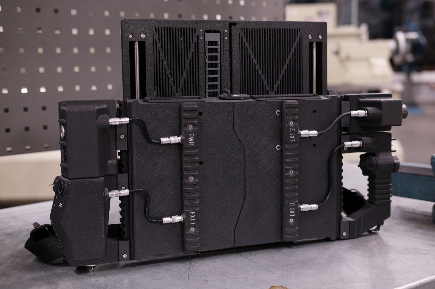
The assembled unit’s rear face carries four labeled rail sockets — PWR, EXT 1, EXT 2, and EXT 3 — clearly visible and legend-molded into the printed rail strips in the finished-build photographs. Each socket mates to a cable from a docked side module through a 0B self-locking connector, the same push-pull circular connector family pictured assembling in Figure 4.9 and specified in Volume 2 §6.1. The chassis build guide describes wiring “the lower rails for power and USB signals” and specifies that the three EXT sockets each get one dedicated USB cable wired to the Raspberry Pi side. Read plainly, that divides the rail cleanly by function: PWR distributes the battery-derived 5.1 V supply outward to docked modules, while EXT1–EXT3 are individually cabled USB pass-throughs, each landing on its own USB connection at the Pi 5 rather than being bused together — meaning a docked module gets a dedicated channel rather than sharing bandwidth or contending for enumeration with its neighbors.
Current capacity for the rail is bounded by two things, not one. The 0B connector family itself is generically rated around 10 A / 500 V for a two-pin configuration in the class Volume 2 §6.1 describes — but that figure describes the family broadly, not the specific listing the upstream build used, and is not a certified rating for this exact part. The tighter, more practically binding constraint is the USB specification and the Pi 5’s own supply behavior: absent a full 5 A PD negotiation (which the DFCD’s battery path does not offer — Volume 2 §1.1, Volume 5), the Pi 5 caps its total USB port budget at 600 mA. A future module designer sizing a new EXT-rail accessory should plan around that USB-class budget, not the connector shell’s theoretical current handling, which is far higher than what the rail will actually deliver in practice.
4.6 Controls and Indicators
4.6.1 Rotary Encoder Wiring
The assembled-unit photographs show a small knurled dial near the trackball housing, consistent in position with where a rotary encoder would sit for one-handed scroll/navigation use alongside the pointing device — but this volume cannot confirm from the photographs alone that this specific control is the encoder rather than one of the other switches, and no upstream wiring diagram for it was retrievable. The GPIO pin assignment is therefore [VERIFY against the upstream schematic, the build video, or the physical unit]. On pull-up resistors: a bare EC11-style encoder (the generic type Volume 2 §7.1 identifies as the likely part, pending confirmation) typically needs pull-ups on its A/B quadrature lines and its switch line unless a breakout board already supplies them — the Pi 5’s GPIO controller can supply these in software without external resistors, so whether the DFCD relies on internal pull-ups or discrete resistors on a control board is also unconfirmed. Its OS-level input mapping, once wired, is covered in Volume 6.
4.6.2 Switch Wiring
The control face visible in the assembled photographs shows more discrete controls than any single retrieved source maps by name: a toggle labeled “COM” near the top edge, a second toggle labeled “S/F” and an integrated handle module labeled “HOR/VER” on the far-left grip — this is very likely the scrolling handle Volumes 1, 3, and 7 describe as mounted but not yet wired, its horizontal/vertical labeling matching its stated panning function even in its current unwired state — a row of seven unlabeled tactile buttons beneath the display, three labeled function keys (“1”, “2”, “3”) beside the display, and further switches near the trackball. This layout is consistent with the parts list in Volume 2 §7.2–7.4 (three 16 mm and one 12 mm momentary switch, ten 12×12 mm tactile buttons, two toggles, one slide switch) without upstream documentation mapping any specific visible control to a specific parts-list line or a specific GPIO pin. This volume will not force that one-to-one assignment where the sources don’t support it.
What is worth noting as an engineering observation rather than a confirmed fact: wiring roughly nineteen or more discrete control lines (ten tactile buttons, the encoder’s two or three lines, three momentary switches, two toggles, one slide switch) directly to the Pi 5’s roughly twenty-eight usable GPIO pins would consume a large share of the header’s capacity and leave little room for anything else. An intermediary I/O expander or a small microcontroller presenting the whole panel as a single USB HID device — the same “macro pad” pattern common in mechanical-keyboard-adjacent projects — would be a reasonable design choice to avoid that pin pressure, but no upstream source confirms this is what the DFCD actually does, and this volume offers it only as a plausible reading, not as fact. Separately, the on-off-on toggle is worth checking against Volume 5’s power path — a toggle of that type is a natural fit for a power-path selector, though again unconfirmed here.
4.6.3 LED Wiring
Four 3 mm LEDs provide status indication, per the hardware list (Volume 2 §7.5), which does not publish color, function, or resistor values, and the wiki pages that would presumably document them returned load errors on every attempt for this and the prior volume. Sizing the current-limiting resistor for each LED is a straightforward calculation once the LED’s forward voltage and rated current are known — R = (V_supply − V_f) / I_f against whichever rail the LEDs are driven from — but this volume does not have those two figures for the specific LEDs used, and will not publish an invented resistor value against unconfirmed inputs. [VERIFY the specific LED forward voltage/current, and the roles each of the four LEDs indicates, against the physical build or upstream documentation.] Volume 2’s guess at plausible roles (power, charging, activity, fault) stands as a guess, not a confirmed mapping.
4.7 Shoulder-Strap Mounts

The DFCD documents its carry hardware directly. The upstream README states that “on the forward facing modules you find mounting points for a shoulder strap,” and the mesh file tree confirms two dedicated printed parts for exactly that — a Sling mount on the right-side (trackball) module and a Strap mount on the left-side (scroll) module (Volume 3 §4.1) — one anchor per side module. This is a separate system from the NATO/picatinny rail clamps that secure the modules themselves to the central computing unit: the wiki home page describes the device as “mounted via NATO rail clamps,” and a dedicated build-guide page gives the clamp assembly — a pivot inserted into the lever with its M3 hole centered, an M3×35 screw passing through the main body and the clamp to thread into the seated pivot, then tightened until the clamp grips the rail. The rail clamps attach the modules to the deck; the two strap-mount parts attach the carry strap.
The assembled-build photographs (Figure 4.1, Figure 4.6, and Figure 1.2 in Volume 1) show a black webbing strap with a side-release-style buckle clipped near the base of the side modules, and Figure 4.7 shows it fitted for carry — consistent with the two per-side Sling mount/Strap mount anchors. Because the strap ties to two points, one on each side module, rather than a single central lug, the deck hangs level when slung rather than tipping toward one side. What the upstream material does not itemize is the strap’s own soft hardware: the webbing, buckle, and any swivel clips are a builder-supplied accessory rather than a listed BOM line — so the printed anchors are confirmed, but the specific strap and buckle remain [VERIFY against the assembled unit; builder’s choice].
On carry balance: the strap attachment visible in the photographs is a single point near one side module, which means the assembled unit will hang lopsided rather than level when carried by the strap alone — worth planning for given the battery, trackball module, and screen assembly are not evenly distributed across the chassis width. No upstream figure gives a weight or balance-point specification, so this is a practical observation rather than a documented recommendation.
4.8 Drag-Chain Cable Management
4.8.1 Cable Bundle Assembly
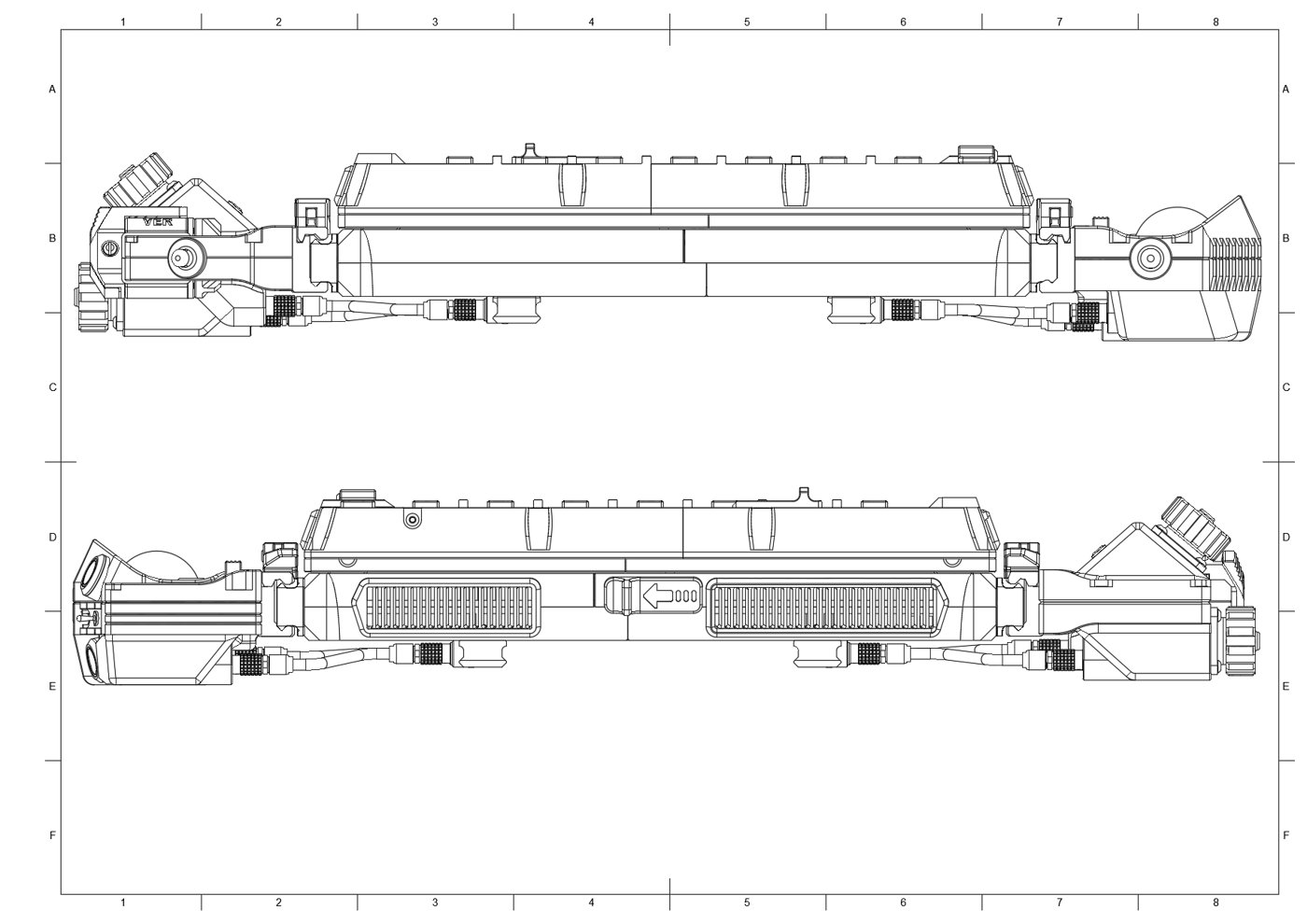
The drag chain is the DFCD’s answer to a problem every sliding-screen design shares: some set of cables has to survive thousands of open/close cycles without fatigue-cracking a conductor, and doing that with loose wire dressing alone is a losing bet over the device’s lifetime. Reading the chassis guide and the screen-unit guide together, the chain is screwed to the chassis at its fixed end and to the screen frame at its moving end, after the screen-side cables — at minimum the micro-HDMI ribbon assembly (Volume 2 §2.2) and the touch digitiser’s USB cable (Volume 2 §2.1) — are connected. The chassis guide’s own phrasing, in the paraphrased form retrieved for this volume, describes the chain as carrying “one HDMI ribbon cable and one USB power cable,” which does not clearly disambiguate whether the screen-mounted tactile buttons and slide switch (§6.2, mounted in the screen frame per the screen-unit guide) share that same USB cable or route through a separate conductor set inside the same chain. [VERIFY the full cable-bundle contents crossing the drag chain — the retrieved wiki summary does not resolve whether the screen-frame controls share the touch-USB cable or use a separate line.] Strain relief at each end is the chain’s own job along its length; at the termini, the cables are secured where they’re screwed down — to the chassis mounting lugs at the fixed end and to the screen frame at the moving end — which functions as the anchor point that keeps flex confined to the chain itself rather than to the cable ends.
4.8.2 Chain Installation
The chain hardware itself is, per the upstream file inventory (Volume 3 §1.3), a modified version of a separately referenced 3D-printable drag-chain design rather than a fully bespoke part — consistent with a builder adapting a known-good mechanism instead of engineering link geometry from scratch. Installation is bracket-to-bracket: one end screws to the chassis, the other to the screen frame, as described above. The link count needed to accommodate the screen’s full travel without binding is not given in the material retrieved for this volume; it is a function of the confirmed-vertical travel distance discussed in §2.1, which itself remains unconfirmed to an exact figure, so the link count is [VERIFY directly from the upstream STEP/mesh files, per Volume 3 §1.3] rather than something this volume will estimate without a travel-distance figure to calculate from.
4.9 Connector Assembly
The four connector families in the DFCD’s hardware list (Volume 2 §6) each need to be assembled — pins crimped or soldered to wire leads, then the shell built up around them — before they can be installed at their chassis interface. None of the reachable upstream sources published a pinout for any of them, so this section documents assembly procedure at the level the connector family supports rather than inventing pin assignments no source confirms.
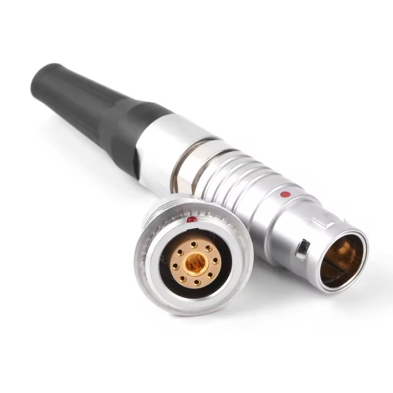
The 0B and 2B self-locking connectors are the same push-pull circular (“aviation connector,” LEMO-style) family at two different shell/pin-count sizes (Volume 2 §6.1–6.2). Assembly follows the pattern pictured in Figure 4.9: individual conductors are crimped or soldered to the connector’s pin/socket contacts, the contacts are seated into the shell in the correct keyed orientation, and the shell halves are assembled around them. Mating is a straight push: aligning the keyway and pushing the plug fully into the socket seats the shell’s spring-finger collar with a positive click, and — this is the point of choosing this family over a friction-fit USB connector at all — the connection only releases when the outer sleeve is deliberately retracted, not from tension or vibration on the cable. The specific pin assignment for each of the DFCD’s six 0B pairs, and for the single 2B pair whose exact chassis location Volume 2 §6.2 already flags as undocumented, remain [VERIFY per Volume 2 §6.1–6.2 or the upstream wiring diagram, once reachable].
The Y2M 8-pin connectors carry multi-conductor signal routing (Volume 2 §6.3). The assembled-unit photographs show a circular multi-pin connector, molded with a “GPIO” legend on the faceplate, at the left-side module position — the same position Volume 1 and Volume 3 identify as the (currently unwired) left connection module. That visual match is consistent with a Y2M pair serving that interface, but it is an inference from photographs, not a confirmed assignment, and the pin-by-pin signal map remains [VERIFY per Volume 2 §6.3].
The pogo pins (GF50-09140-4024, Volume 2 §6.4) provide spring-loaded contact rather than a plug-socket mating, which fits best at a docking or hinge interface where a full connector shell isn’t practical — plausibly somewhere along the screen slider or a module-docking face, given that is exactly the kind of joint pogo-style contacts are chosen for elsewhere in the industry. The DFCD’s specific interface for these two pins is not confirmed by any source reachable for this volume and is [VERIFY].
4.10 Final Checks Before First Power-On
Before the Pi 5 or the battery is ever connected for the first time, the following checks reduce the risk of damaging either — and, given both are the two most expensive and least field-replaceable components in the build, they are worth the few extra minutes even under time pressure:
- Battery polarity. Verify polarity at the battery bay’s contact plate with a multimeter before the NP-F pack is inserted, rather than trusting the pack’s own blade keying alone (§4.1) — the keying protects against inserting the pack backward, not against a miswired contact plate behind it.
- Step-down output voltage. Measure the Joy-it PiEnergy Mini’s output directly at its output leads, with the Pi 5 disconnected, and confirm a steady 5.1 V before wiring it onward (§4.2). Given the module’s wide 6–36 V input tolerance, a fault on the input side will not necessarily be obvious without this direct measurement.
- Power-button wiring. Confirm the separate power-button leads described in §4.3 are correctly connected to the Pi 5’s power-button header before first power-on — a miswired power-button line is unlikely to damage anything, but it is easier to trace with the chassis open than after final assembly.
- USB connections verified before the Pi 5 is installed. Check the keyboard, trackball, touch digitiser, and rail EXT1–EXT3 connections for correct seating and continuity before the Pi 5 board itself goes into its cooler and chassis mount — the Pi 5 is the single hardest component to reach once the chassis is closed, so any USB fault is far cheaper to find beforehand.
- Screen slide travel with cables routed. With the drag chain installed and every screen-side cable connected (HDMI ribbon, touch USB, and any screen-frame control wiring per §8.1), slide the screen through its full travel and confirm nothing binds, snags, or pulls taut at either end — this is dramatically easier to fix with the chassis still open than after the final assembly screws are in.
- Rail connector seating. Confirm the 0B connectors joining the trackball module (and, once wired, the left connection module) to the PWR/EXT rail sockets have fully seated their self-locking collars (§5, §9) before closing the chassis.
None of these checks require special equipment beyond a multimeter, and none should be skipped in the interest of getting to a first boot sooner — the entire point of a modular, serviceable chassis is undermined if a wiring fault gets discovered only after the case is closed.
Comments (0)