DFCD · Volume 2
Bill of Materials & Sourcing
Every purchased component in the DFCD reference build, with sourcing notes and substitution options
2.1 Compute Platform
2.1.1 Raspberry Pi 5 (8 GB)
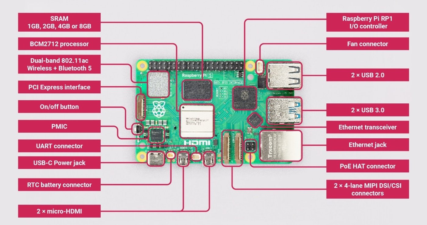
The reference build uses a Raspberry Pi 5 with 8 GB of LPDDR4X-4267 RAM — one step above the 4 GB base SKU and one below the 16 GB “power user” board Raspberry Pi sells for developer and content-creation workloads. For the DFCD’s job — opening FreeCAD assemblies of moderate complexity for reference, measurement, and light editing at the bench — 8 GB is the sensible middle: FreeCAD’s memory use scales with document complexity (sketches, bodies, tessellated viewport meshes), and a document with a few dozen linked parts can use several gigabytes once the OS and desktop are also loaded. 4 GB leaves little room for a browser tab or PDF viewer alongside FreeCAD; 16 GB buys capacity this shop-floor use case doesn’t need.
The Pi 5’s Broadcom BCM2712 SoC pairs a quad-core 2.4 GHz Cortex-A76 CPU (512 KB per-core L2, 2 MB shared L3) with a VideoCore VII GPU supporting OpenGL ES 3.1 and Vulkan 1.3 — roughly double the Pi 4’s single-thread throughput, which is the main reason FreeCAD is viable here at all. This volume treats the Pi 5 as a bill-of-materials line item rather than a platform deep-dive; the PiFlux subproject elsewhere in this Cyberdecks hub (../../PiFlux/) covers Pi 5 architecture, memory bandwidth, and thermal behavior at depth, and readers wanting that story should start there.
One platform detail does bear directly on this volume: the Pi 5 is designed around USB-C Power Delivery and will request a 5 V/5 A (25 W) PDO when offered, falling back to 3 A otherwise — and capping total USB port power at 600 mA when it can’t negotiate the full 5 A. The DFCD’s battery path (§5.2) does not offer a PD-negotiated 5 A supply, which matters for the keyboard/trackball/touch budget and is worked through fully in Volume 5.
2.1.2 Joy-it Raspberry Pi 5 Cooler
The reference build uses the Joy-IT aluminum case with active cooling for the Raspberry Pi 5 (manufacturer part RB-AlucaseP5-01B; Kjell & Co’s retail listing, linked from the upstream hardware list, carries local part number 88410). It’s a two-piece aluminum enclosure — a finned top section (69 × 56 × 15.5 mm) clamping onto the SoC and RP1 I/O controller as a heatsink, and a bottom section (87 × 56 × 7.5 mm) — with an integrated fan, four mounting screws, and a 120 g assembled weight. The listing’s own thermal figures show roughly 30 °C idle and 51 °C full load, comfortable margin for a warm workshop.
Mechanically, the case’s compact footprint — Joy-IT markets it as needing no more clearance than a bare Pi 5 board — is what lets it fit the DFCD’s central compute module at all; a full-size active tower would not fit the chassis envelope defined in the upstream STEP files. Builders substituting a different cooler should check its footprint against the central module’s internal clearance before ordering, since Volume 3’s print dimensions are built around this specific case.
2.2 Display
2.2.1 10.1-inch IPS Touch LCD
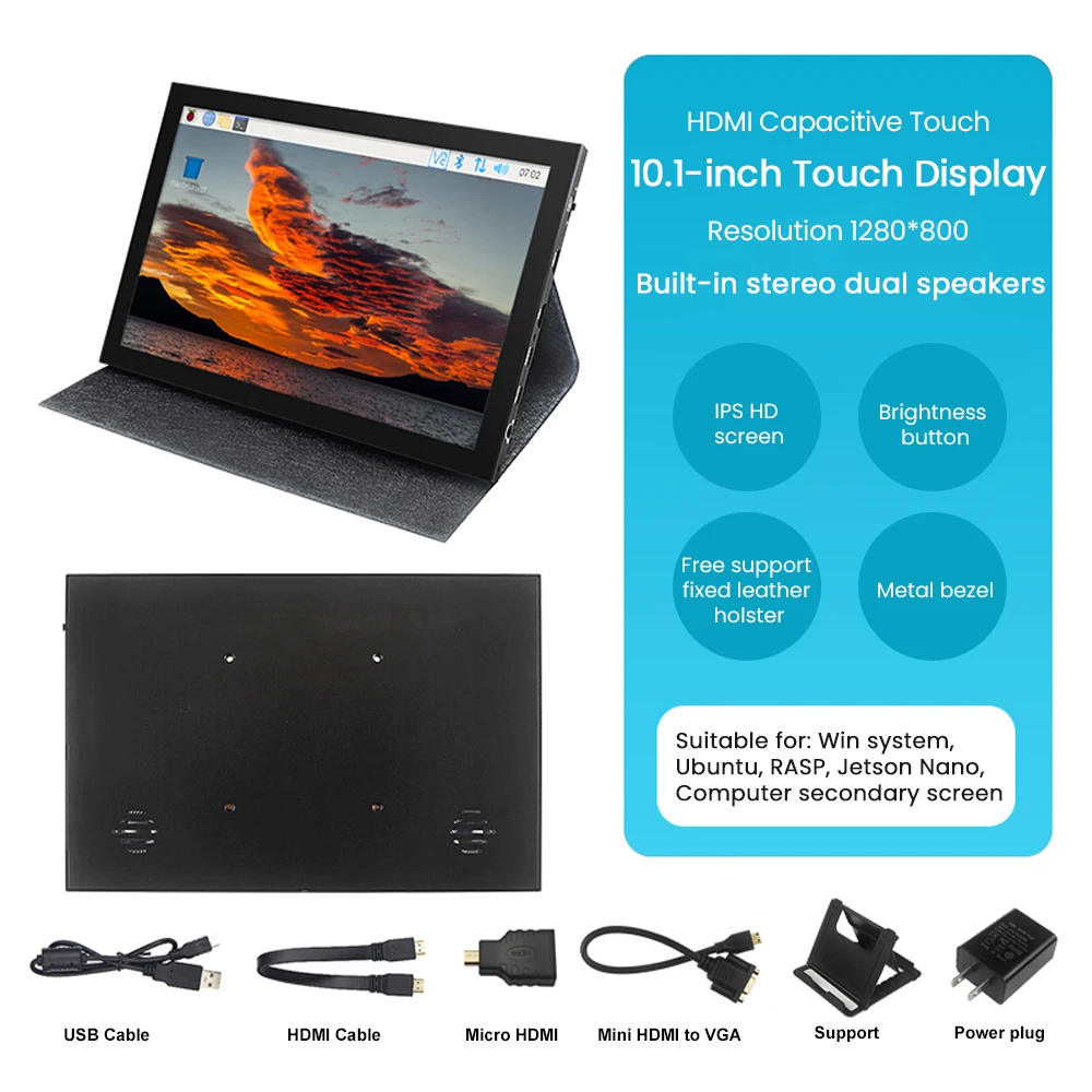
The reference build uses a 10.1-inch IPS touch LCD from an AliExpress listing linked directly in the upstream hardware list. Automated retrieval of that listing was blocked (a login redirect, then a rate-limit response on retry), so the exact resolution and touch-controller part number can’t be confirmed against the seller’s own page here. What can be said with confidence: the 10.1-inch IPS-panel-with-HDMI-input category this listing belongs to — the same reference design sold as Waveshare’s 10.1inch Capacitive Touch Screen LCD and SunFounder’s 10-inch DIY touchscreen, among others — is built almost universally around a 1280×800 IPS panel with capacitive touch reported over a separate USB cable as a driver-free HID device (5- or 10-point multitouch, no kernel driver on current Raspberry Pi OS). Given the upstream build pairs the panel with a plain HDMI video path and calls out no special touch driver, this is very likely what the DFCD’s panel implements — but it remains [VERIFY against the specific listing at build time] rather than a certified spec, and a builder should confirm the panel needs both an HDMI cable and a separate USB cable.
Table 1 — 2.1 10.1-inch IPS Touch LCD
| Parameter | Value | Confidence |
|---|---|---|
| Panel type | IPS, 10.1” diagonal | Confirmed (upstream hardware list) |
| Resolution | Typically 1280×800 for this product class | Category-typical, not confirmed against the exact listing |
| Touch | Capacitive, USB HID, driver-free | Category-typical, not confirmed against the exact listing |
| Video input | HDMI (via the ribbon assembly, §2.2) | Confirmed |
A 10.1-inch panel of this class runs roughly 240 × 165 mm including the driver-board bezel, and that footprint is what the sliding rail is sized around in the upstream chassis STEP files (Volume 3). A builder substituting a different panel should verify its bezel outline against the rail slot rather than assume a drop-in fit from diagonal size alone.
2.2.2 Micro HDMI to Ribbon Cable Assembly
One of the Pi 5’s two micro-HDMI ports routes to the display through a 90-degree micro-HDMI adapter terminating in a 50 cm flexible ribbon cable, per the upstream hardware list. The right-angle geometry matters mechanically: a straight plug would force a large, rigid bend right at the connector inside tight chassis clearances, and repeated flexing near the plug is exactly where micro-HDMI cables fail first — the adapter turns that into a fixed joint instead of a stress point.
At 50 cm and this resolution class, signal integrity is not a practical concern — well within HDMI’s unequalized cable-length tolerance. The flexible ribbon form factor is the detail that matters for the DFCD specifically: the cable has to survive the screen’s travel on its sliding rail across the device’s operating life, and a flat ribbon-style cable tolerates repeated flex-and-fold far better than a round, shielded HDMI cable of the same length. The upstream drag-chain parts (Volumes 3–4) manage this cable alongside the touch-USB and power wiring that also cross the slider joint.
2.3 Keyboard
2.3.1 NOS 450 TKL Mechanical Keyboard
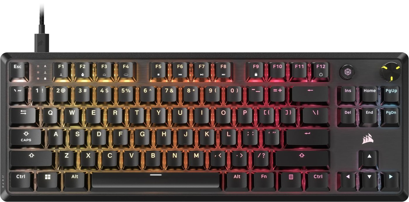
The upstream hardware list’s line item reads “1 x NOS 450 TKL keyboard” and links to an Elkjøp listing for the NOS C-450 Mini Pro RGB mechanical gaming keyboard. Confirmed across several independent retailer listings (Gadcet, Currys, Student Computers, CompuOne): Outemu Red mechanical switches — linear, no tactile bump, rated for roughly 50 million keystrokes — wired USB-A, RGB backlighting with 18 effect modes, NKRO/anti-ghosting, onboard profile memory.
There’s a genuine naming tension worth flagging rather than smoothing over: every independent retailer describes the NOS C-450 Mini Pro as a 60%-class board (62 keys), not tenkeyless. TKL conventionally keeps the function row and arrow cluster and only drops the numpad — noticeably wider than a 60% layout, which drops those too. This may be loose upstream terminology, or the build may use a different, unlisted NOS variant with a larger footprint. Either way, a builder should confirm the exact key count and footprint against the physical unit before committing to Volume 3’s print dimensions for the keyboard well — a 60% board and a true TKL board are meaningfully different widths, and the chassis slot is cut to one specific footprint.
Whichever layout it turns out to be, the integration logic is the same: the board sits in a recessed well beneath the sliding screen’s rail, low-profile enough for the screen to retract fully over it, and connects to the Pi 5 as a standard USB HID keyboard with no special driver. The RGB is cosmetic; a builder prioritizing simplicity over per-key lighting could substitute any sufficiently low-profile USB keyboard of matching footprint with no electrical changes, only a chassis-fit check.
2.4 Trackball
2.4.1 Harvested Logitech Marble Electronics
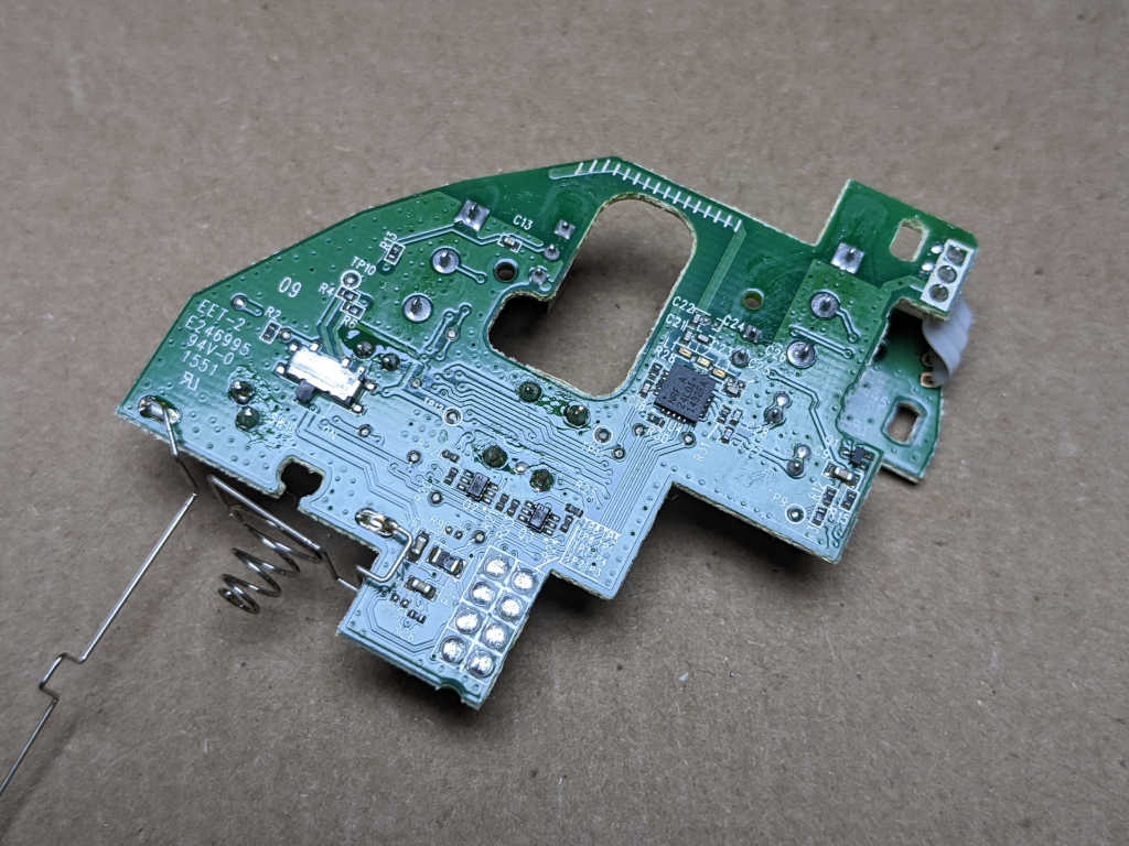
The trackball module reuses the sensor and control electronics harvested from a Logitech Trackball Marble rather than a purpose-built cyberdeck trackball PCB, mounted inside the DFCD’s own printed right-side module in place of the Marble’s original shell — a “donor device” approach common in cyberdeck builds that repurposes a mature, already-solved input device instead of engineering a sensor and controller from scratch.
The upstream wiki pages that would presumably document the harvest procedure, the exact Marble revision, and the mounting details returned server errors on every attempt made for this volume (the chassis, clamp, and screen-unit build-guide pages were all unreachable). The specific harvest steps and mounting are therefore [VERIFY against the upstream wiki once reachable, or against the build video]. Generally: Logitech’s Marble line used an optical rotation sensor on a small internal PCB wired to a USB host, and a harvest of this kind typically means desoldering the ball-cage sensor assembly intact and re-mounting it behind a new ball cutout with the USB leads re-routed — plausibly what the DFCD does, but not confirmed. Volume 4 is the reference for the mechanical mounting sequence once that gap closes.
2.4.2 Custom Trackball Electronics (Planned)
The upstream project frames the harvested-Marble approach as interim, with a purpose-built trackball PCB noted as a future replacement. No schematic, sensor part number, or timeline has been published beyond that stated intent, and this volume will not invent one. Practically: the harvest approach above is the only working trackball path today, and a builder should plan on sourcing a donor Marble rather than waiting on unreleased electronics. Volume 7 tracks this alongside the DFCD’s other work-in-progress items.
2.5 Power System
2.5.1 NP-F Battery (10050 mAh)
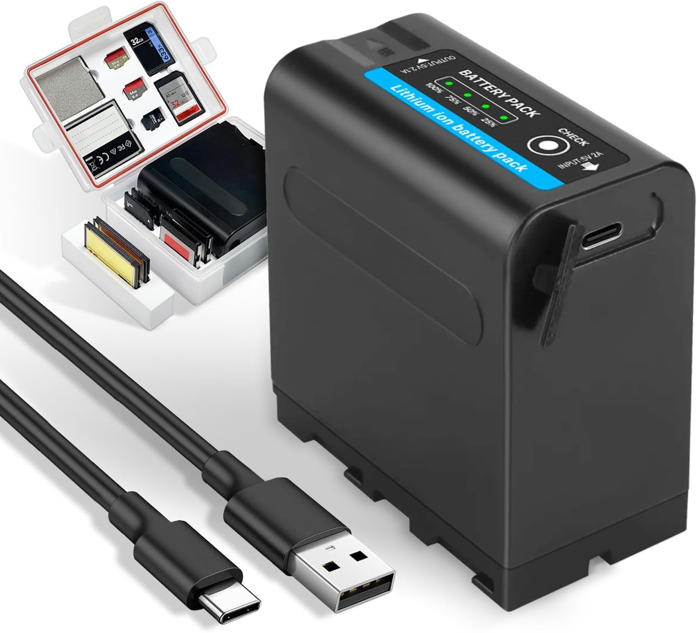
The battery is a Jupio NP-F970, 10,050 mAh, with a built-in USB-C charging input — confirmed from the Scandinavian Photo (Norway) listing linked upstream. NP-F is a Sony camcorder/video-light battery form factor, not a bespoke part: the “L-series” shells (NP-F550/F770/F970, smallest to largest) have been an industry-standard footprint in video production for decades, so NP-F-shaped batteries and mounts are widely available from many third-party makers, not just Sony. The Jupio pack is a third-party cell in the largest (F970) shell built out to 10,050 mAh — well above stock F970 capacity, a common practice for third-party packs aimed at video lights and monitors. Nominal output is 7.2 V, typical for a 2-cell pack in this format.
The built-in USB-C input is what makes this pack convenient here: it recharges directly over USB-C rather than needing an NP-F-specific charger cradle. The listing didn’t publish the input’s charge voltage/current rating in content retrieved for this volume, so the charge rate is [VERIFY against the unit’s markings or Jupio’s datasheet]; given the pack’s 72.4 Wh energy content, a full recharge over a typical 5 V USB-C source will take a meaningful number of hours, which Volume 5 works through against realistic charging patterns. Physically, the pack’s NP-F contact blades mate to the step-down module’s input leads in the power module — the same contact scheme used across the NP-F ecosystem, part of why the form factor suits a printed chassis bay.
2.5.2 Joy-it Step-Down Module (7.2 V → 5.1 V)
The step-down module is the Joy-IT PiEnergy Mini (RB-PE01), matching the Kjell & Co listing (local part 88409). Confirmed spec: 6–36 V DC input, regulated 5.1 V output at up to 3 A, built around an STM8S001J3 microcontroller with a GPIO4 interface to the host, a pre-mounted heatsink, an integrated on/off pushbutton, and a 2-pin 2.54 mm fan header. The board is tiny — 23 × 56 × 11 mm, 15 g.
This is where the Pi 5’s own appetite (§1.1) matters: official guidance is a 5 V/5 A (25 W) PD supply for full performance, falling back to a 600 mA USB budget cap without one. The PiEnergy Mini’s 3 A ceiling means the DFCD’s battery path is a fixed, non-negotiating regulator below the Pi’s ideal supply point — a reasonable tradeoff for a battery device (25 W continuous would hurt runtime anyway), but it means the keyboard/trackball/touch budget sharing the 5.1 V rail needs checking against what’s left after the Pi 5’s own draw, not assumed generous. Volume 5 works through that budget and the resulting runtime math; Volume 4 documents the module’s physical placement and wiring to the Pi 5.
2.6 Connectors and Wiring
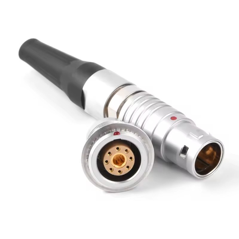
2.6.1 0B Self-Locking Connectors
Six male/female pairs of 0B-series push-pull self-locking circular connectors (the FGG/EGG “aviation connector” family, per the linked AliExpress listing) carry power and signal across the DFCD’s modular joints, notably the rear USB power/signal rails where detachable modules dock to the core chassis. This connector family — the same basic push-pull-lock series used across LEMO-style camera and instrumentation cabling — has a well-documented generic spec across multiple vendor listings for the class: roughly 10 A / 500 V AC for a 2-pin configuration with 18 AWG-class wire capacity. That describes the 0B series broadly rather than the specific listing linked upstream, whose own page couldn’t be retrieved, so treat it as representative rather than a certified rating for this exact part.
The locking mechanism explains the choice over a plain USB connector: pushing the plug in seats spring fingers that grip the socket, and pulling the cable only tightens the grip — deliberate retraction of the outer shell is required to disconnect. For a harness inside a chassis with moving parts (the slider, the drag-chain), that resistance to accidental disconnection under vibration or snag is a real advantage over a friction-fit connector worked loose over years of field use.
2.6.2 2B Self-Locking Connector
One 2B-series self-locking connector pair (female plug variant, per the upstream list) is used — a larger shell/pin-count size than 0B, for a single higher-current or multi-conductor joint rather than the smaller 0B pairs used elsewhere. Its exact location and function within the harness isn’t detailed in the parts list itself; Volume 4’s wiring diagram is the reference for its placement.
2.6.3 Y2M 8-Pin Connectors
Two male/female Y2M 8-pin connector pairs handle multi-conductor signal routing between modules — the right choice where several discrete signals (a set of switch or LED lines, or an encoder’s multiple contacts) need to cross a module boundary through one mated joint rather than several single-conductor connectors. The upstream list publishes no pinout, so the signal assignment on each conductor is [VERIFY against Volume 4’s wiring diagram or the upstream build documentation].
2.6.4 Pogo Pins (GF50-09140-4024)
Two GF50-09140-4024 pogo pins provide spring-loaded contact at a module interface — plausibly a docking or hinge point where a plug/socket pair isn’t practical. Retailer listings (Amazon, eBay) confirm the part as a “high current” spring-loaded pogo pin in the GF series, but a datasheet with contact force, travel, and current rating could not be located for this volume; those figures are [VERIFY against a manufacturer datasheet or physical measurement]. Volume 4 documents which chassis interface the two pins serve.
2.7 Controls and Indicators
2.7.1 Rotary Encoder with Click
A single rotary encoder with an integrated pushbutton provides scroll/navigation input — most likely scrolling a FreeCAD viewport or file browser, with the shaft click as select/confirm. The upstream list links a generic AliExpress encoder without a manufacturer part number or detent count, so the exact electrical spec is [VERIFY against the physical part or listing at order time]. Generic encoders sold for enclosure/hobbyist use are near-universally the common 20-detent incremental quadrature type (“EC11-style”), a reasonable working assumption pending confirmation. Its software mapping is covered in Volume 6.
2.7.2 Momentary Switches
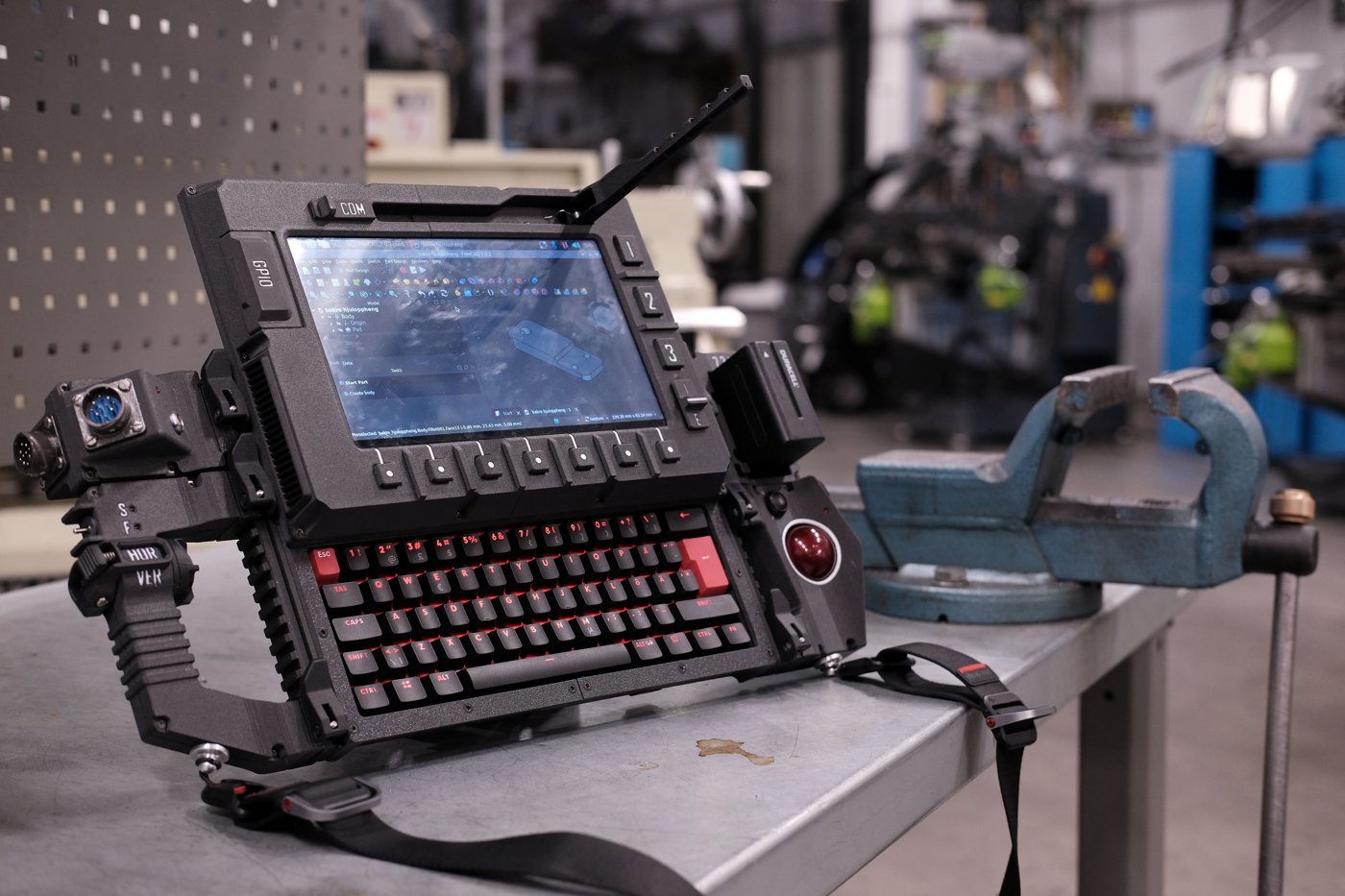
Three 16 mm momentary switches and one 12 mm momentary switch provide dedicated function inputs (the button column beside the trackball in Figure 2.7). The upstream list itemizes size and type but not a function-assignment map, so the specific role of each switch is [VERIFY against the upstream build documentation or the assembled unit’s software configuration]. Momentary switches are typically reserved for actions that shouldn’t persist if released — plausibly a wake button plus FreeCAD-specific and general-purpose shortcuts — but this volume assigns no specific function the upstream sources don’t document.
2.7.3 Tactile Buttons
Ten 12×12 mm tactile buttons form a secondary input grid, plausibly on a small PCB near the encoder and momentary switches as a macro-key panel. As above, function map and PCB layout are [VERIFY against Volume 4’s wiring documentation], which is where the GPIO or intermediary-microcontroller wiring for these ten buttons belongs.
2.7.4 Toggle Switches and Slide Switch
One 6 mm on-on toggle, one 6 mm on-off-on momentary toggle, and one 2-position slide switch round out the mode-selection controls. Unlike the momentary switches, these hold position after release — the natural choice for settings that should persist without holding a button down, such as a power-path selector or peripheral enable line. Their specific function in the reference build is [VERIFY against the upstream build documentation]; Volume 4 documents their wiring, and Volume 5 is worth checking if any sit in the battery/power path (plausible for an on-off-on toggle).
2.7.5 LEDs
Four 3 mm LEDs provide status indication. The upstream list gives quantity and package size but not color or role, and neither could be confirmed — the wiki pages that would presumably document this returned load errors. A plausible but unconfirmed set of roles would be power/on, charging status, activity, and fault/mode — common practice on similar SBC builds — but this is a guess, not a documented fact, and remains [VERIFY against the physical build or upstream documentation].
2.8 Chassis and Print Materials
2.8.1 Material Selection
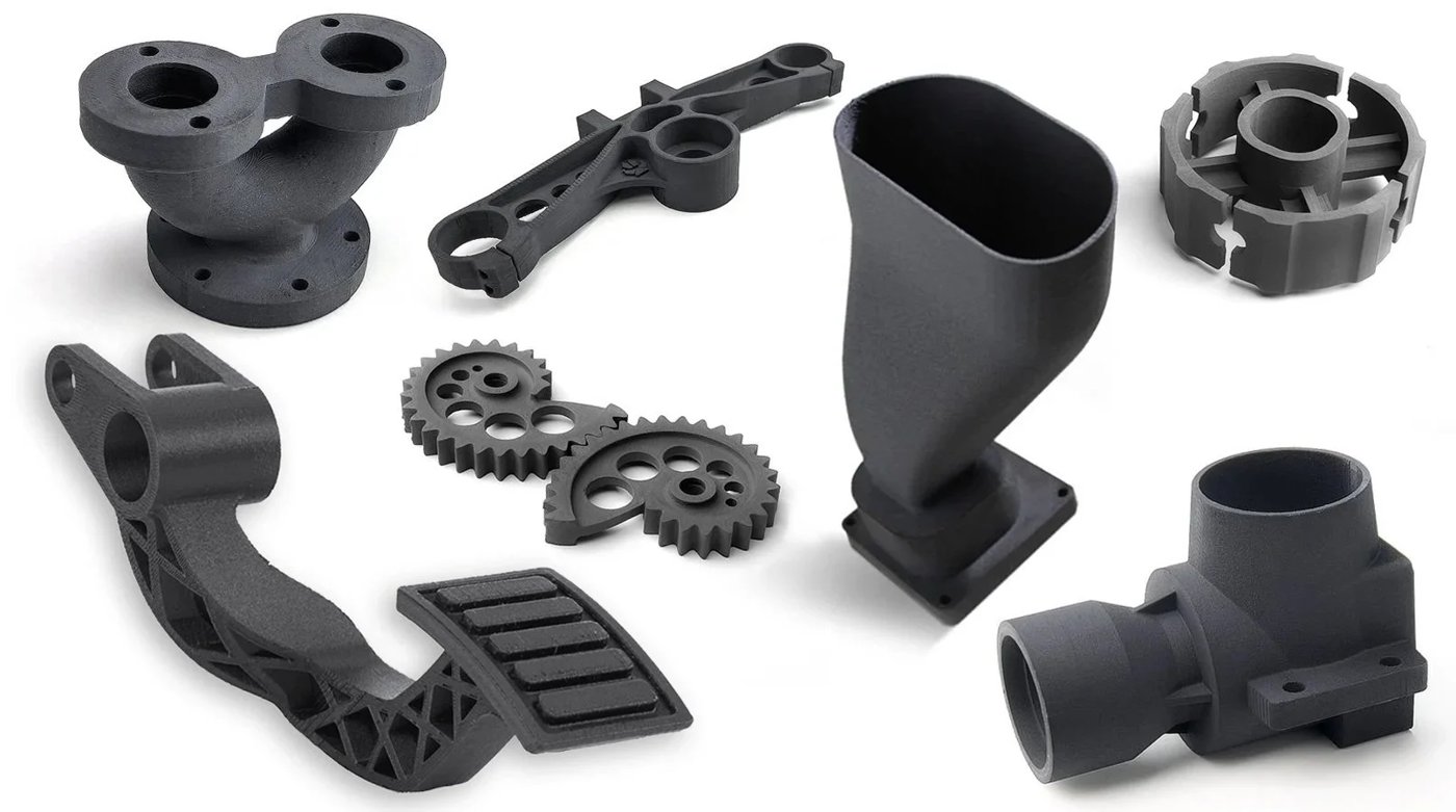
The entire chassis — central compute module, trackball module, display slider, and the currently unwired left connection module and scrolling handle — is printed from the upstream STEP and mesh files. The upstream repository does not, in material accessible for this volume, mandate a single print material; the wiki’s “build guide chassis” page returned server errors on every attempt, so the reference build’s actual material is [VERIFY against the upstream wiki once reachable, or against the build video].
Absent a confirmed spec, the general tradeoffs apply as they would to any structural enclosure destined for a workshop rather than a climate-controlled office: PLA prints easily but softens well below typical summer workshop temperatures (glass transition around 60 °C) and is least forgiving near a heat source or in direct sun. PETG is a meaningfully better fit for a shop tool — better heat resistance and impact tolerance than PLA on the same hardware, at the cost of slightly fussier tuning. ASA/ABS push heat and impact resistance further but need an enclosed, heated chamber to avoid warping, and ABS needs ventilation. Given the DFCD is explicitly designed to live in “a warm workshop environment” (Volume 1), PETG is the pragmatic default absent a confirmed upstream spec, with PLA acceptable for a first prototype and ASA/ABS reserved for builders equipped to handle them. Volume 3 carries this into slicer settings and post-processing.
2.8.2 Print Hardware (Inserts, Fasteners)
The upstream hardware list, as retrieved here, itemizes only purchased electronic and electromechanical parts — no separate line for structural fastening hardware (heat-set inserts, screws, standoffs) that a chassis this complex would typically need. This is [VERIFY against the upstream wiki’s chassis build guide, currently unreachable, or the assembly video]; this volume will not invent insert sizes or thread pitches the upstream project hasn’t published.
Generally, brass heat-set inserts (commonly M2 or M3 at this scale) pressed into printed bosses, paired with matching machine screws, are the standard approach for any joint expected to be assembled and disassembled more than once — a hole threaded directly in plastic strips out quickly under repeated servicing. Given the DFCD’s modular design anticipates modules being detached and reattached, inserts at the module attachment points would be the expected choice, but a builder should confirm against Volume 3 and upstream documentation before ordering fasteners.
2.9 Sourcing Notes and Substitutions
The upstream hardware list sources most components from a small set of predominantly European vendors: RS Online (Norway) for the Pi 5, Kjell & Co for both Joy-IT modules, Elkjøp for the keyboard, Scandinavian Photo for the Jupio battery, and AliExpress for the display, connectors, and controls/indicators. Listed prices are in euros and the retail links resolve to Norwegian storefronts, consistent with a Scandinavia-based upstream author. Builders elsewhere should expect to substitute regional equivalents for the Kjell/Elkjøp/Scandinavian Photo items; the AliExpress-sourced parts are already globally available by the nature of that marketplace.
Compute and cooling (§1) are the least sourcing-sensitive: the Pi 5 is stocked by essentially every major electronics distributor worldwide, and Joy-IT sells directly at joy-it.net as well as through resellers (Kjell, Rapid Electronics, Varia Store, Elektor) across multiple countries — RB-PE01 and RB-AlucaseP5-01B are the right search terms regardless of region.
Display (§2) carries the most substitution flexibility and the most risk of a silent spec mismatch: the 10.1-inch IPS-touch-HDMI category is sold under many names (Waveshare, SunFounder, generic AliExpress OEM) on what appears to be a near-identical reference design, but bezel dimensions and touch behavior can still vary between nominally identical listings — verify the bezel footprint against Volume 3’s chassis dimensions before printing.
Keyboard (§3) sourcing is comparatively narrow: the NOS C-450 Mini Pro is a European-market SKU (also seen at UK retailers like Gadcet, Currys, Student Computers) rather than a globally standard part the way a Pi 5 is. Given the TKL-vs-60% discrepancy noted in §3.1, a builder outside NOS’s home market may reasonably source a different low-profile mechanical keyboard matched to the chassis footprint rather than chase the exact SKU.
Trackball (§4) sourcing depends on finding a donor Logitech Trackball Marble secondhand — a long-discontinued but historically high-volume product, generally available through used-electronics marketplaces, though supply will thin as builds like this one consume donor units. This is the component most exposed to future scarcity, part of why the upstream roadmap (§4.2, Volume 7) targets a custom PCB that removes the dependency.
Power (§5): the Jupio NP-F970 is a third-party battery in a widely available form factor; any reputable NP-F970-shell battery with USB-C input and comparable capacity is a viable substitute, since the mechanical/electrical interface is standardized across the ecosystem, not proprietary to Jupio. The PiEnergy Mini is sold directly and through multi-country resellers, so lead-time risk is low.
Connectors and controls (§6–7) are all generic AliExpress-sourced categories (push-pull aviation connectors, pogo pins, tactile buttons, toggle/slide switches, 3 mm LEDs) with many equivalent listings from different sellers — matching the stated size/pin-count/type matters more than the specific listing when substituting, and lead times from this class of sourcing should be planned in weeks rather than days.
Overall, the bill of materials is sourcing-realistic rather than aspirational: every confirmed part is either a mainstream SBC-ecosystem product (Pi 5, Joy-IT modules) or a commodity part available from multiple sellers, with the keyboard and trackball the two items most likely to need a builder-specific substitution depending on region and secondhand-market luck. Volumes 3 (Printing the Chassis) and 4 (Assembly & Wiring) are the next stops for turning this parts list into a working device.
Comments (0)